Rainbow Electronics AT86RF211 User Manual
Page 31
31
AT86RF211
1942C–WIRE–06/02
•
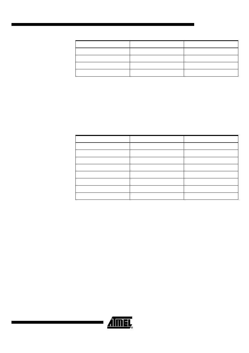
Datatol Programming
The tolerance for the extraction of DATA rate must be nearly 2% of the RATE. The toler-
ance represents the step for the calculation of the rate.
If the tolerance is too high, rate value is reached earlier but the rate value could be
unstable (step too big).
If the tolerance is too low, it could be difficult to catch up the DATA and the clock recov-
ery could get lost.
Some tolerance values given for example, with tolerance = 2% x DATARATE:
•
PLL Lock Detect
The PLL lock function uses UP and DOWN signals from the internal phase detector.
These signals are analyzed synchronously with a clock frequency, depending of LDCK
bit programming (10 MHz or 20 MHz sampling).
LDCK is set to ‘1’ to double the clock frequency of the function PLL lock detect, to
increase the precision of the function.
N0LD2 triggers the unlock condition of the PLL.
N0LD2 = number of consecutive edges of the sampling clock with UP and DOWN active
before considering PLL unlocked.
This value must not be set to 0 or 1. The recommended value is default value, i.e. 2.
N1LD2 triggers the lock condition of the PLL.
N1LD2 = number of cycle at the PLL reference frequency, without any unlock condition
before considering PLL locked.
This value must not be set to 0.
It is recommended to use default values indicated in the table.
(1067)
10
9.6 kbps
1 bit ~ 1067 x T
(2135)
10
4.8 kbps
1 bit ~ 2135 x T
(4269)
10
2.4 kbps
1 bit ~ 4269 x T
(10246)
10
1 kbps
1 bit ~ 10246 x T
DATATOL[7:0]
Rate
Period
(3)
10
64 kbps
1 bit ~ 3 x T
(4)
10
50 kbps
1 bit ~ 4 x T
(vv)
10
……
1 bit ~ vv x T
(20)
10
10 kbps
1 bit ~ 20 x T
(21)
10
9.6 kbps
1 bit ~ 21 x T
(43)
10
4.8 kbps
1 bit ~ 43 x T
(85)
10
2.4 kbps
1 bit ~ 85 x T
(205)
10
1 kbps
1 bit ~ 205 x T
DATARATE[13:0]
Rate
Period