Status register – Rainbow Electronics AT86RF211 User Manual
Page 33
33
AT86RF211
1942C–WIRE–06/02
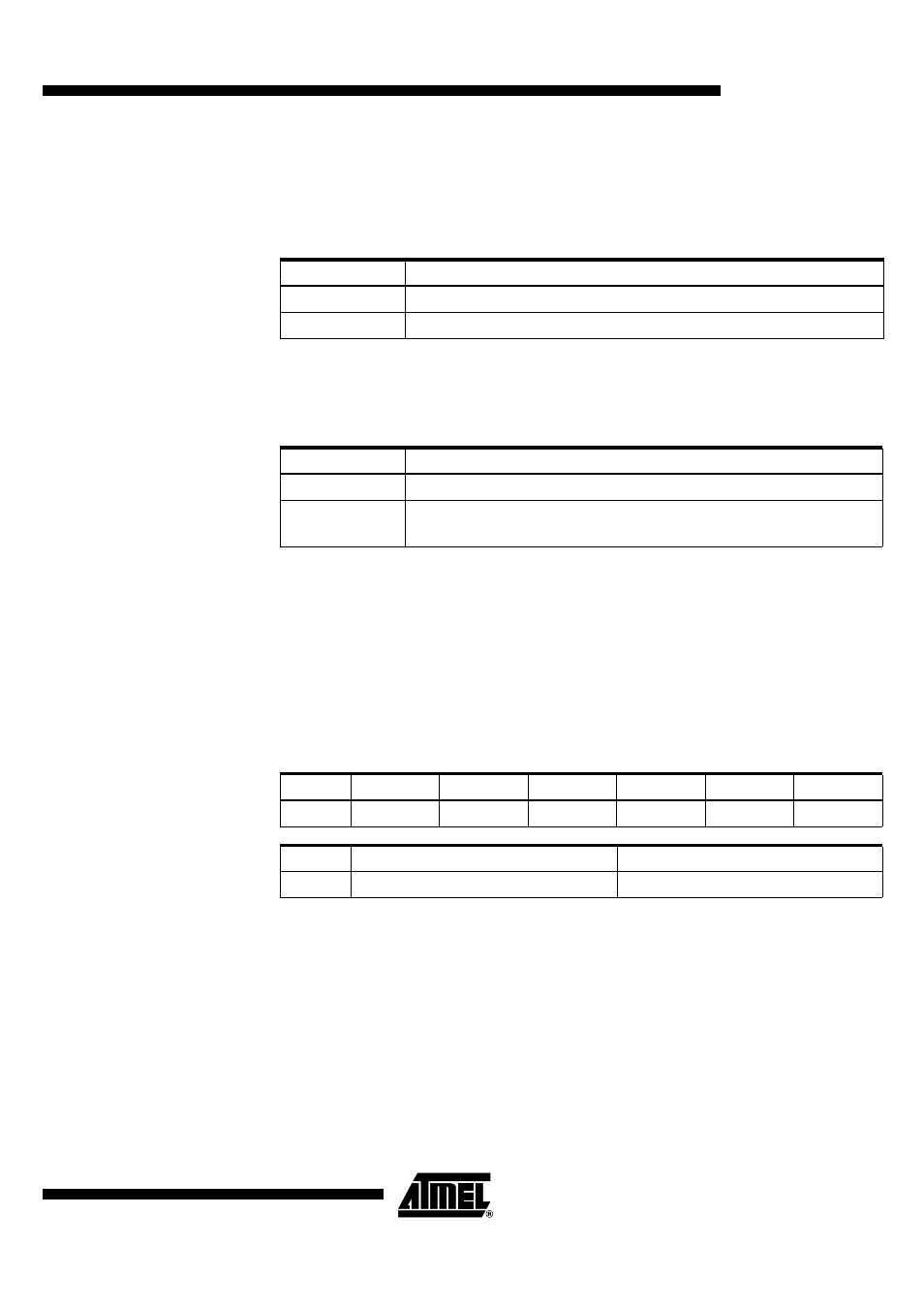
In reception mode, only one frequency needs to be programmed. In transmission mode,
two different registers (F0 & F1), or (F2 & F3) must be programmed for “0” code and “1”
code transmission. The DATAMSG pin value actually selects the used register. The four
registers can also be set to define two channels, so that the AT86RF211 may switch
quickly from a channel to the other.
Example:
FCHANNEL = 868.3 MHz
IF1 = 10.7 MHz
Deviation = ± 4 kHz
Notes:
1. In reception mode, one of the two frequencies (879 MHz or 857.6 MHz) can be cho-
sen, taking into account external parameters (for example, the noise that brings the
image frequency).
2. Two frequencies are used to transmit data: 868.304 MHz for ”
1
” transmission and
868.296 MHz for ”
0
” transmission. The polarity of DATAMSG can be swapped using
bit 5 of CTRL1.
Status Register
The STATUS register is used to read the status of internal functions (including the
wake-up function) or the output value of the internal ADC. This register can only be
read.
Mode
Programmed Frequency
RX
FCHANNEL ± IF1
TX
FCHANNEL ± deviation
Mode
FSK
RX
868.3 ± 10.7 = 879 MHz or 857.6 MHz programmed in F2
TX
868.3 ± 0.004 = 868.304 MHz programmed in F1 when DATAMSG = “1”
and 868.296 MHz programmed in F0 when DATAMSG = “0”
Table 10. Status Register Overview
Name
PLLL
MRSSI
MVCC
WAKEUP
-
MSGERR
nbit
30
29-24
23-18
17
16
15
Name
MSGDATL
MSGMRATE
nbit
14-10
9-0