If1 filtering, If1 gain and second mixer – Rainbow Electronics AT86RF211 User Manual
Page 12
12
AT86RF211
1942C–WIRE–06/02
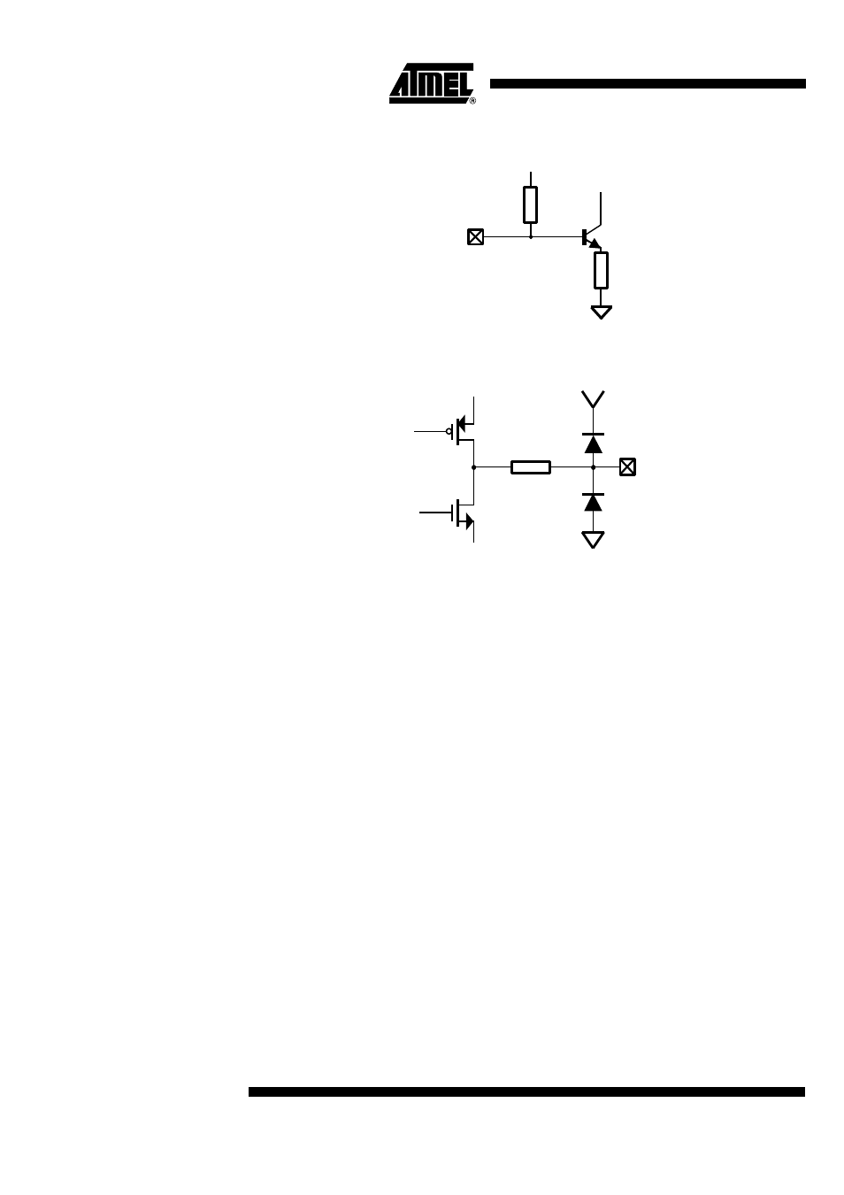
Figure 11. Schematic Input of the LNA
Figure 12. Schematic Output of the Mixer
The first mixer translates the input RF signal down to 10.7 MHz or 21.4 MHz as chosen
by the user. The local oscillator is provided by the same synthesizer which will generate
a local frequency 10.7 MHz or 21.4 MHz away from the Tx carrier frequency.
The output impedance of the mixer is 330
Ω
with a 20% accuracy, so that low cost, stan-
dard 10.7 MHz ceramic filters can be directly driven. Other IFs may be chosen thanks to
the high bandwidth (50 MHz) of the mixer.
IF1 filtering
A popular ceramic filter is used to reject the second image frequency and provide a first
level of filtering.
The IF1 filter can however be removed; it leads to a sensitivity reduction of about 3 dB
(the substitution coupling capacitor should be > 100 pF).
IF1 Gain and Second Mixer
The input impedance of the IF1 amplifier is naturally 330
Ω
to match the input filter. The
voltage gain, i.e. gain at 10.7 MHz or 21.4 MHz added to the conversion gain at 455 kHz
is typically 14 dB when loaded by 1700
Ω
. The second mixer operates at a fixed LO fre-
quency of 10.245 MHz or 20.945 MHz. Its output impedance is 1700
Ω
in parallel with 20
pF.
RXIN
IF1OUT