First lna/mixer – Rainbow Electronics AT86RF211 User Manual
Page 11
11
AT86RF211
1942C–WIRE–06/02
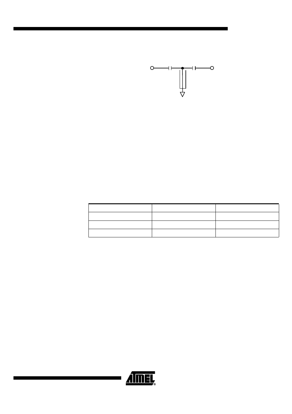
Figure 10. TEM Filter
Such a filter also provides an out-of-band interference rejection greater than 20dB,
40 MHz away from 433 MHz.
First LNA/Mixer
The main characteristics of the LNA/Mixer are typically:
•
Voltage gain: 17 dB for the LNA/Mixer; 11 dB if gain min. is selected
•
Bandwidth: 1.2 GHz
•
Noise figure of LNA alone: 3 dB at 900 MHz, best matching
•
Noise figure of LNA + mixer:
8 dB at 900 MHz, with maximum gain and best matching
12 dB at 900 MHz, with minimum gain and best matching
•
1 dB compression point: -20 dBm at the input of LNA
•
Matching:
Notes:
1. RXIN: impedance to be seen by LNA input for NF optimization purpose
2. SWOUT: output impedance of the RF switch
The gain is programmable through bit 25 of CTRL1 register (6dB attenuation when min
gain is selected). The choice for the matching between the SWITCH and the LNA
depends mainly on the chosen SAW filter. Usually in/out impedance of SAW filters is
50
Ω
, but other ones can be implemented and the matching network recalculated thanks
to the previous impedance table.
The LNA is directly coupled to the first mixer. Input and output of the LNA/Mixer must be
connected through a capacitive link because of their internal DC coupling. A SAW or
ceramic filter provides such a link.
1 pF
1 pF
Zc = 7
Ω
l = 0.75
(19 mm)
λ
/4
TEM
Table 2. Matching Information
Frequency Band
RXIN
433 MHz
35 + j 170
Ω
24 - j 43
Ω
868 MHz
37 + j 85
Ω
50 - j 42
Ω
915 MHz
30 + j 85
Ω
50 - j 42
Ω