Software control, Control logic, Serial data interface – Rainbow Electronics AT86RF211 User Manual
Page 22
22
AT86RF211
1942C–WIRE–06/02
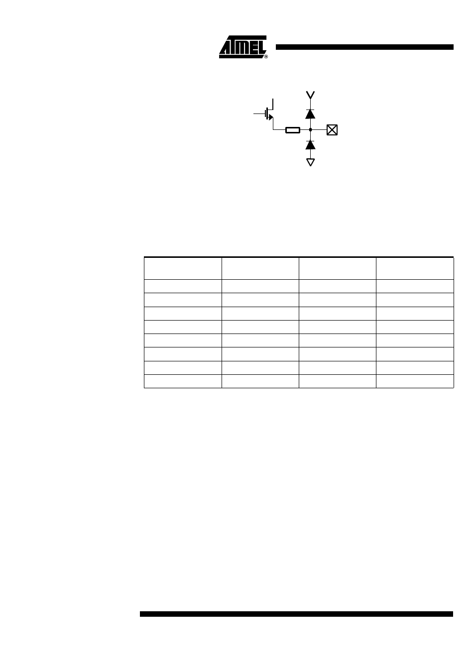
Figure 28. R
POWER
Input Schematic
Note:
Keeping the PA output matched guarantees maximum power efficiency.
Software Control
The power can then be adjusted, from the value set by R
POWER
down to a maximum of
12 dB below, by programming the bits 6 to 8 of the CTRL1 register. So, 8 levels are dig-
itally selectable with a variation of the output power. The minimum regulated output
power is set to -10 dBm.
Note:
Unless otherwise specified, typical data given for R
POWER
= 18 k
Ω
, T = 25°C, V
CC
= 3 V
Control Logic
Serial Data Interface
The application microcontroller can control and monitor the AT86RF211 through a syn-
chronous, bidirectional, serial interface made of 3 wires:
•
SLE: enable input
•
SCK: clock input
•
SDATA: data in/out
When SLE = ‘1’, the interface is inhibited, i.e. the SCK and SDATA (in) values are not
propagated into the IC, reducing the power consumption and preventing any risk of par-
asitic write or read cycle.
A “read” or “write” cycle starts when SLE is set to ‘0’ and stops when SLE is set to ‘1’.
Only one operation can be performed in one access cycle: only one register can be
either read or written.
R
POWER
100
Ω
Table 3. Software Control of the Power Level
TXLVL (CTRL1)
Pout at 433 MHz
(dBm)
Pout at 868 MHz
(dBm)
Pout at 915 MHz
(dBm)
000
0
-2
-3
001
4
0
0
010
6
3
2
011
8
5
4
100
10
7
5
101
11
8
7
110
12
9
8
111
13
10
9