Overview and choice of intermediate frequencies, Rx - tx switch, Image rejection and rf filter – Rainbow Electronics AT86RF211 User Manual
Page 10
10
AT86RF211
1942C–WIRE–06/02
Overview and Choice of
Intermediate Frequencies
For selectivity and flexibility purpose, a classical and robust 2 IF superheterodyne archi-
tecture has been selected for the AT86RF211. In order to minimize the external
components cost, the most popular IF values have been chosen. The impedances of the
input/output of the mixing stages have been internally matched to the most usual
ceramic filter impedances.
Two typical IF values are suggested:
•
10.7 MHz is the most popular option.
•
21.4 MHz: the image frequency is far enough from the carrier frequency to enable
the use of a front-end ceramic filter instead of a SAW filter. It is also noticeable that
21.4 MHz quartz filters usually have more abrupt slopes than 10.7 MHz ceramic
filters.
Rx - Tx Switch
A SPST switch is integrated. In the transmission mode, it protects the LNA input from
the large voltage swings of the PA output (up to several volts peak-to-peak), which is
switched to a high impedance state. It is automatically turned ON or OFF by the RX/TX
control bit. The insertion loss is about 2 dB and the reverse isolation about 30 dB in a
300
Ω
environment.
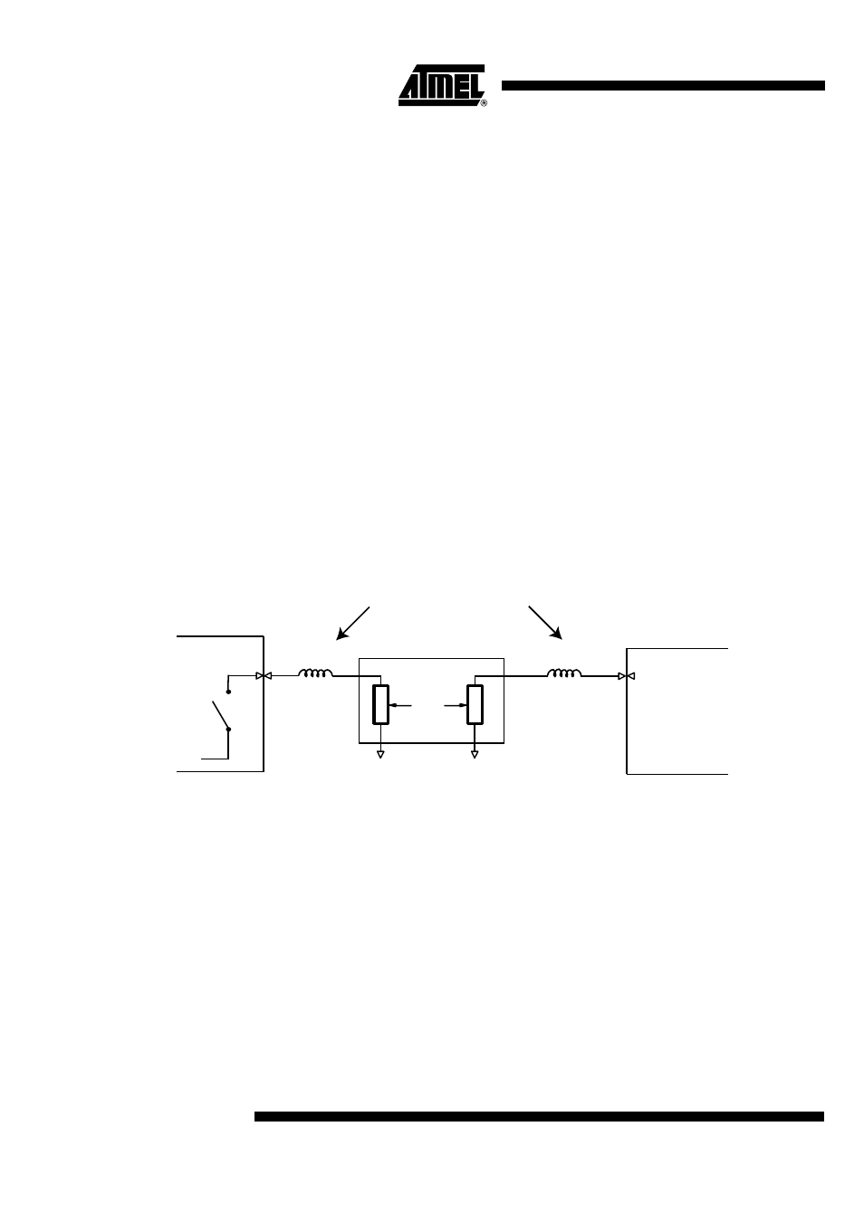
Image Rejection and RF Filter
The immunity of the AT86RF211 can be improved with an external band-pass filter.
For example, when using a SAW Filter, this device must be matched with the LNA input
and the switch output. The following scheme gives the typical implementation for an
868 MHz application with a 50
Ω
/50
Ω
SAW filter.
Figure 9. Typical 50
Ω
SAW Filter Implementation in the 868 MHz Band
See Table 2 for precise matching information.
The SAW filter can be replaced by a TEM ceramic, helicoidal or a ceramic coax
λ
/4 res-
onator designed as a narrow band-pass filter. For instance, with an IF selected at
10.7 MHz, a -3 dB bandwidth of 5 MHz, with an insertion loss of 1 dB and an image
rejection of 12 dB can be achieved with the following:
RXIN
SPST Switch
50
Ω
12 nH
2.2 nH
SWOUT (pin 48)
(pin 45)
SAW
These inductors can be printed