Rainbow Electronics AT86RF211 User Manual
Page 18
18
AT86RF211
1942C–WIRE–06/02
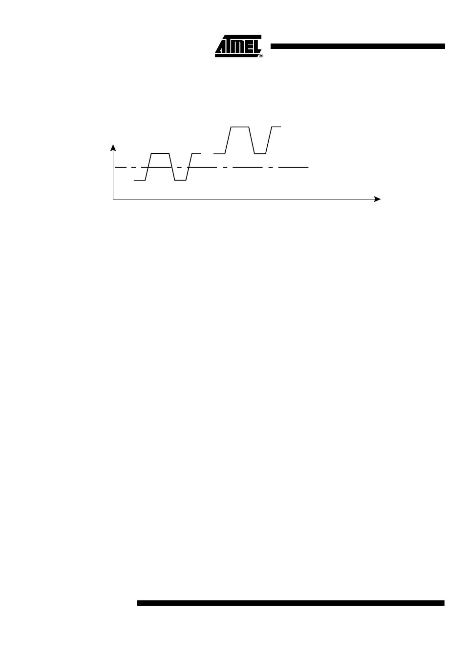
To operate this way, the user must make sure that the "0" and "1" level at the output of
the discriminator are "on both sides" of the comparison level in order for the decision to
be made properly.
Figure 22. How to Set Up the Data Slicing Parameters
To set the discriminator and the Data Slicer accordingly:
–
It is possible to measure the output DC level of the discriminator DISCOUT
(thanks to the A/D embedded converter)
–
DTR[1:0] make it possible to shift (up or down) the DC level at the output of
the discriminator :
- DTR[1] = 1: +180 mV + 77x (V
CC
- 2.4V)
- DTR[0] = 1: -180 mV - 77x (V
CC
- 2.4V)
–
DTR[5:2] make it possible to tune the comparison threshold around V
CC
/2.
16 levels are possible, with a LSB = 15 mV per Volt of supply voltage. V
CC
/2
corresponds to DTR[5:2] = 0111, and the RESET value is 1000.
These procedures can be made automatically by software. Please refer to the applica-
tion note.
DISCOUT:
demodulated
data
Not OK
Comparator threshold
Time
OK