Figure 50. tx operation (t_mode = 0) – Rainbow Electronics ATA5812 User Manual
Page 59
59
ATA5811/ATA5812 [Preliminary]
4689B–RKE–04/04
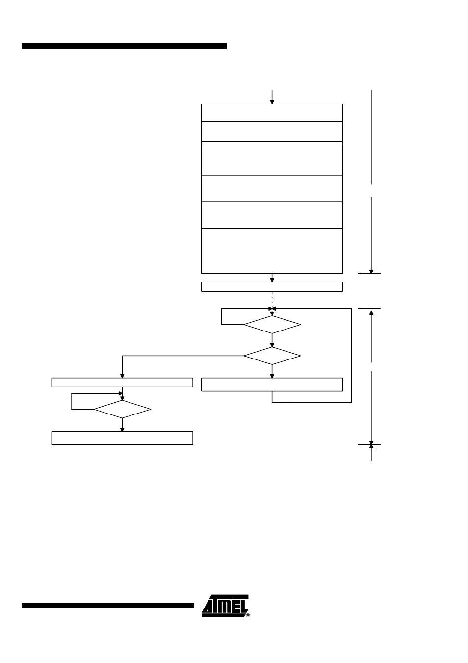
Figure 50. TX Operation (T_MODE = 0)
N
Write Control Register 6
Baud1, Baud0:
Select Baudrate Range
Lim_max0 ... Lim_max5:
Don't care
Write Control Register 5
Lim_min0 ... Lim_min5:
Select the baud rate
Bitchk0, Bitchk1:
Don't care
Write Control Register 4
XLim:
Select the baud rate
ASK/_NFSK:
Select modulation
Sleep0 ... Sleep4:
Don't care
XSleep:
Don't care
Write Control Register 3
FR7, FR8:
VSOUT_EN:
Set VSOUT_EN = 1
CLK_ON:
Don't care
Write Control Register 2
FR0 ...FR6:
Adjust f
RF
P_mode:
Enable or disable the
Manchester modulator
Write Control Register 1
IR1, IR0:
Select an event which activates
an interrupt
AVCC_EN:
Don't care
FS:
Select operating frequency
OPM1, OPM0:
Set OPM1 = 0 and OPM0 = 1
T_mode:
Set T_mode = 0
Write TX/RX Data Buffer (max. 16 byte)
Pin IRQ = 1 ?
Y
N
TX more Data
Bytes ?
Y
Write TX/RX Data Buffer (max. 16 - number of bytes still in
the TX/RX Data Buffer)
Command: Delete_IRQ
N
Pin IRQ = 1 ?
Y
Write Control Register 1
OPM1, OPM0:
Set IDLE
Idle Mode
Start-up
Mode (TX)
T
Startup
= 331,5
×
T
DCLK
TX Mode
Idle Mode
Adjust f
RF