Matching network in tx mode, Matching network in rx mode – Rainbow Electronics ATA5812 User Manual
Page 21
21
ATA5811/ATA5812 [Preliminary]
4689B–RKE–04/04
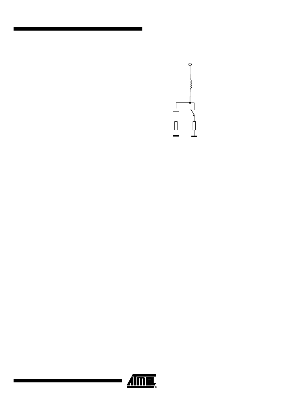
Figure 17. Equivalent Circuit of the Switch
Matching Network in TX
Mode
In TX mode the 20
mm long and 0.4
mm wide transmission line which is much shorter
than
λ
/4 is approximately switched in parallel to the capacitor C
9
to GND. The antenna
connection between C
8
and C
9
has an impedance of about 50
Ω
locking from the trans-
mission line into the loop antenna with pin RF_OUT, L
2
, C
10
, C
8
and C
9
connected
(using a C
9
without the added 7.6
pF as discussed later). The transmission line can be
approximated with a 16
nH inductor in series with a 1.5
Ω
resistor, the closed switch can
be approximated according to Table 10 on page 20 with the series connection of 1.6 nH
and 5
Ω
in this mode. To have a parallel resonant high impedance circuit with little RF
power going into it looking from the loop antenna into the transmission line a capacitor of
about 7.6 pF to GND is needed at the beginning of the transmission line (this capacitor
is later absorbed into C
9
which is then higher as needed for 50
Ω
transformation). To
keep the 50
Ω
impedance in RX mode at the end of this transmission line C
7
has to be
also about 7.6 pF. This reduces the TX power by about 0.5 dB at 433.92 MHz compared
to the case the where the LNA path is completely disconnected.
Matching Network in RX
Mode
In RX mode the RF_OUT pin has a high impedance of about 7
k
Ω
in parallel with 1.0 pF
at 433.92
MHz as can be seen in Table 11 on page 22. This together with the losses of
the inductor L
2
with 120 nH and Q
L2
= 25 gives about 3.7 k
Ω
loss impedance at
RF_OUT. Since the optimum load impedance in TX mode for the power amplifier at
RF_OUT is 890
Ω
the loss associated with the inductor L
2
and the RF_OUT pin can be
estimated to be 10
×
log(1 + 890/3700) = 0.95 dB compared to the optimum matched
loop antenna without L
2
and RF_OUT. The switch represents, in this mode at
433.92 MHz, about an inductor of 1.6 nH in series with the parallel connection of 2.5 pF
and 2.0 k
Ω
. Since the impedance level at pin RX_TX1 in RX mode is about 50
Ω
this
only negligiblably dampens the received signal by about 0.1 dB. When matching the
LNA to the loop antenna the transmission line and the 7.6 pF part of C
9
has to be taken
into account when choosing the values of C
11
and L
1
so that the impedance seen from
the loop antenna into the transmission line with the 7.6 pF capacitor connected is 50
Ω
.
Since the loop antenna in RX mode is loaded by the LNA input impedance the loaded Q
of the loop antenna is lowered by about a factor of 2 in RX mode hence the antenna
bandwidth is higher than in TX mode.
1.6 nH
RX_TX1
2.5 pF
11
Ω
TX
5
Ω