Rainbow Electronics ATA5812 User Manual
Page 14
14
ATA5811/ATA5812 [Preliminary]
4689B–RKE–04/04
Table 6 shows the blocking performance measured relative to -100 dBm for some other
frequencies. Note that sometimes the blocking is measured relative to the sensitivity
level (dBS) instead of the carrier (dBC).
The ATA5811/ATA5812 can also receive FSK and ASK modulated signals if they are
much higher than the I1dBCP. It can typically receive useful signals at 10 dBm. This is
often referred to as the nonlinear dynamic range which is the maximum to minimum
receiving signal which is 116 dB for 20 kBaud Manchester. This value is useful if two
transceivers have to communicate and are very close to each other.
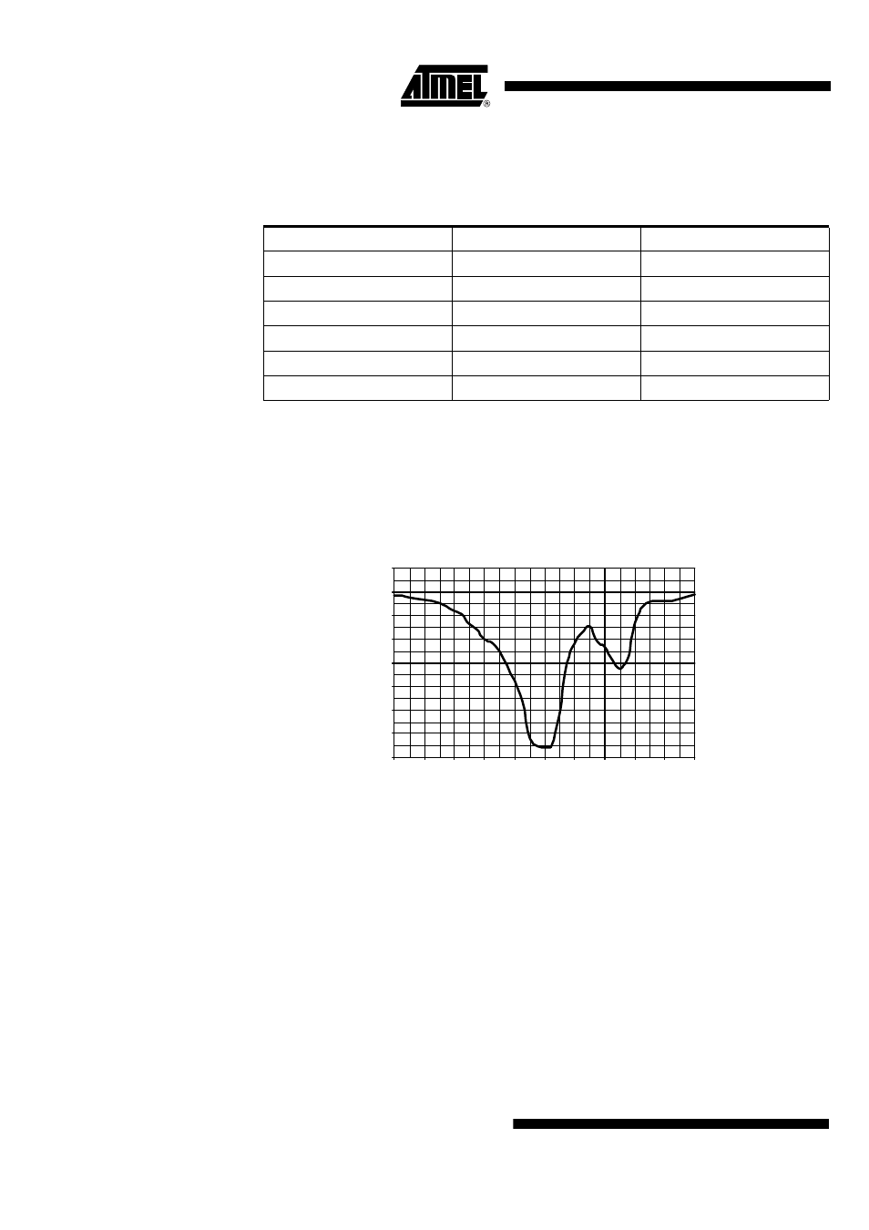
Figure 11. Close In 6 dB Blocking Characteristic and Image Response at 433.92 MHz
This high blocking performance makes it even possible for some applications using
quarter wave whip antennas to use a simple LC band-pass filter instead of a SAW filter
in the receiver. When designing such an LC filter take into account that the 3 dB block-
ing at 433.92 MHz/2 = 216.96 MHz is 43 dBC and at 433.92 MHz/3 = 144.64 MHz is
48 dBC and at 2
×
(433.92 MHz + 226 kHz) + -226 kHz = 868.066 MHz/868.518 MHz is
56 dBC. And especially that at 3
×
(433.92 MHz + 226 kHz)+226 kHz = 1302.664 MHz
the receiver has its second LO harmonic receiving frequency with only 12 dBC blocking.
Inband Disturbers, Data
Filter, Quasi Peak
Detector, Data Slicer
If a disturbing signal falls into the received band or a blocker is not continuous wave the
performance of a receiver strongly depends on the circuits after the IF filter. Hence the
demodulator, data filter and data slicer are important in that case.
Table 6. Blocking 6 dB Above Sensitivity Level with BER < 10
-3
Frequency Offset
Blocker Level
Blocking
+0.75 MHz
-45 dBm
55 dBC/61 dBS
-0.75 MHz
-45 dBm
55 dBC/61 dBS
+1.5 MHz
-38 dBm
62 dBC/68 dBS
-1.5 MHz
-38 dBm
62 dBC/68 dBS
+10 MHz
-30 dBm
70 dBC/76 dBS
-10 MHz
-30 dBm
70 dBC/76 dBS
-10.0
0.0
10.0
20.0
30.0
40.0
50.0
60.0
70.0
-1.0
-0.8
-0.6
-0.4
-0.2
0.0
0.2
0.4
0.6
0.8
1.0
Distance of Interfering to Receiving Signal [MHz]
B
locking Level [
d
B
C
]