Preliminary, Can controller mailbox and registers organization, Sfr’s on-chip can controller registers – Rainbow Electronics T89C51CC02 User Manual
Page 69
Rev.A - May 17, 2001
69
Preliminary
T89C51CC02
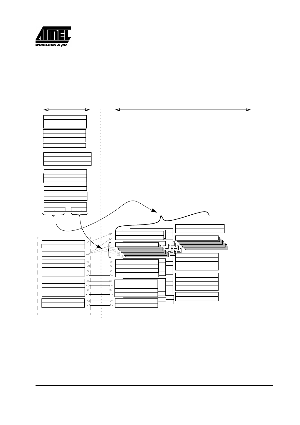
15.3. CAN Controller Mailbox and Registers Organization
A pagination allows management of the 48 registers and the 32 (4x8) bytes of the mailbox via 28SFR’s.
All actions on message object window SFRs are reflected to the corresponding message object registers.
Figure 57. CAN Controller memory organization
Ch.3 - ID Tag - 1
Ch.3 - ID Tag - 2
Ch.3 - ID Tag - 4
Ch.3 - ID Tag - 3
Ch.3 - ID Mask - 1
Ch.3 - ID Mask - 2
Ch.3 - ID Mask - 4
Ch.3 - ID Mask - 3
Ch.3 - Message Data - byte 0
General Control
General Status
Bit Timing - 1
Bit Timing - 2
Bit Timing - 3
Enable Interrupt
Enable Interrupt message object
Page message object
message object Status
message object Control & DLC
Message Data
ID Tag - 1
ID Tag - 2
ID Tag - 4
ID Tag - 3
ID Mask - 1
ID Mask - 2
ID Mask - 4
ID Mask - 3
message object 0 - Status
message object 0 - Control & DLC
Ch.0 - ID Tag - 1
Ch.0 - ID Tag - 2
Ch.0 - ID Tag - 4
Ch.0 - ID Tag - 3
Ch.0 - Message Data - byte 0
message object 3 - Status
message object 3 - Control & DLC
Status Interrupt message object
(message object number) (Data offset)
SFR’s
on-chip CAN Controller registers
4 message objects
8 bytes
TimStmp High
TimStmp Low
Ch.0 - ID Mask- 1
Ch.0 - ID Mask- 2
Ch.0 - ID Mask - 4
Ch.0 - ID Mask- 3
CANTimer High
CANTimer Low
TimTTC High
TimTTC Low
TEC counter
REC counter
Timer Control
Enable message object
message object Window SFRs
Ch.0 TimStmp High
Ch.0 TimStmp Low
Ch.3 TimStmp High
Ch.3 TimStmp Low
General Interrupt