interrupt system, introduction, Preliminary – Rainbow Electronics T89C51CC02 User Manual
Page 121: Interrupt system, Introduction
Rev.A - May 17, 2001
121
Preliminary
T89C51CC02
18. Interrupt System
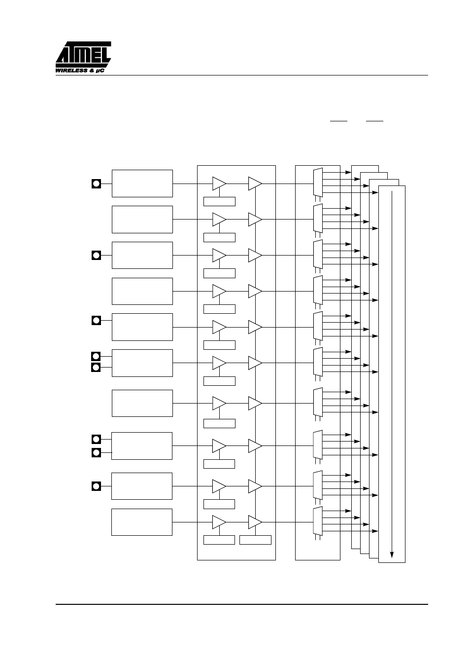
18.1. Introduction
The CAN Controller has a total of 10 interrupt vectors: two external interrupts (INT0 and INT1), three timer
interrupts (timers 0, 1 and 2), a serial port interrupt, a PCA, a CAN interrupt, a timer overrun interrupt and an
ADC. These interrupts are shown below.
Figure 126. Interrupt Control System
ECAN
IEN1.0
EX0
IEN0.0
00
01
10
11
External
Interrupt 0
INT0#
EA
IE0.7
EX1
IEN0.2
External
Interrupt 1
INT1#
ET0
IEN0.1
Timer 0
EC
IEN0.6
PCA
ET1
IEN0.3
Timer 1
ES
IEN0.4
UART
EADC
IEN1.1
A to D
Converter
ETIM
IEN1.2
CAN Timer
CAN
Interrupt Enable
Lowest Priority Interrupts
Highest
Priority Enable
00
01
10
11
00
01
10
11
00
01
10
11
00
01
10
11
00
01
10
11
00
01
10
11
00
01
10
11
00
01
10
11
Priority
Interrupts
TxDC
RxDC
AIN1:0
IPH/L
controller
Timer 2
00
01
10
11
ET2
IEN0.5
TxD
RxD
CEX0:5
- MAX5151 (16 pages)
- MAXQ3108 (64 pages)
- MAX5661 (39 pages)
- MAX6691 (7 pages)
- MAX5362 (12 pages)
- ADC10158 (26 pages)
- MAX8922L (14 pages)
- MAX8596Z (8 pages)
- MAX7491 (18 pages)
- MAX15040 (15 pages)
- MAX5177 (16 pages)
- ADC08138 (22 pages)
- MAX5961 (42 pages)
- T89C51RD2 (86 pages)
- MAX16055 (9 pages)
- MAX6659 (17 pages)
- ADC0820 (20 pages)
- MAX6678 (19 pages)
- MAX8884Z (15 pages)
- MAX16915 (9 pages)
- MAX8620 (18 pages)
- MAX5144 (12 pages)
- MAX6670 (8 pages)
- MAX8760 (39 pages)
- W78C32C (14 pages)
- MX7533 (8 pages)
- MAX8727 (13 pages)
- MAX9053 (15 pages)
- W78C54 (16 pages)
- MAX8614B (15 pages)
- W90N740 (219 pages)
- MAX6626 (13 pages)
- ADC10738 (30 pages)
- MAX17000 (31 pages)
- MAX5051 (21 pages)
- MAXQ1004 (18 pages)
- MAX6871 (51 pages)
- MX7847 (12 pages)
- MAX6608 (6 pages)
- MAX17083 (15 pages)
- MAX6641 (17 pages)
- MAX5251 (16 pages)
- MAX6338 (8 pages)
- MAX6690 (16 pages)
- MAX8668 (18 pages)