ac parameters, explanation of the ac symbols, serial port timing - shift register mode – Rainbow Electronics T89C51CC02 User Manual
Page 133: Preliminary, Ac parameters
Rev.A - May 17, 2001
133
Preliminary
T89C51CC02
19.4. AC Parameters
19.4.1. Explanation of the AC Symbols
Each timing symbol has 5 characters. The first character is always a “T” (stands for time). The other characters,
depending on their positions, stand for the name of a signal or the logical status of that signal. The following is
a list of all the characters and what they stand for.
T
A
= -40
°
C to +85
°
C; V
SS
= 0 V; V
CC
= 5 V
±
10% ; F = 0 to 40 MHz.
T
A
= -40
°
C to +85
°
C; V
SS
= 0 V; V
CC
= 5 V
±
10%.
(Load Capacitance for all outputs = 60 pF.)
Table 29 give the frequency derating formula of the AC parameter for each speed range description. To calculate
each AC symbols. take the x value and use this value in the formula.
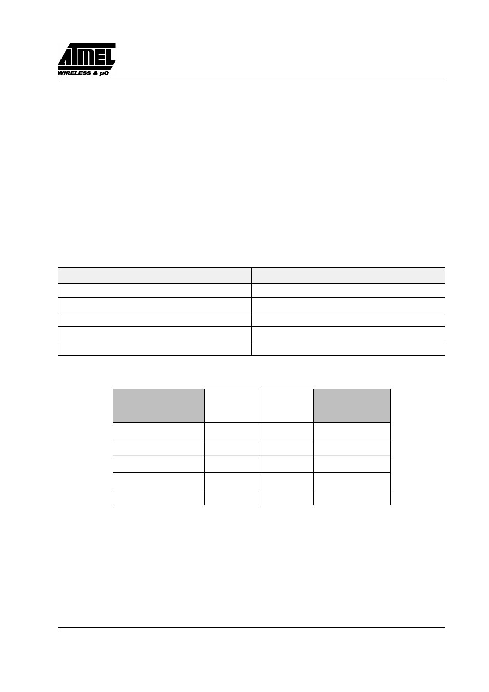
19.4.2. Serial Port Timing - Shift Register Mode
Table 27. Symbol Description (F= 40 MHz)
Symbol
Parameter
T
XLXL
Serial port clock cycle time
T
QVHX
Output data set-up to clock rising edge
T
XHQX
Output data hold after clock rising edge
T
XHDX
Input data hold after clock rising edge
T
XHDV
Clock rising edge to input data valid
Table 28. AC Parameters for a Fix Clock (F= 40 MHz)
Symbol
Min
Max
Units
T
XLXL
300
ns
T
QVHX
200
ns
T
XHQX
30
ns
T
XHDX
0
ns
T
XHDV
117
ns