registers, Preliminary, Registers – Rainbow Electronics T89C51CC02 User Manual
Page 119
Rev.A - May 17, 2001
119
Preliminary
T89C51CC02
17.9. Registers
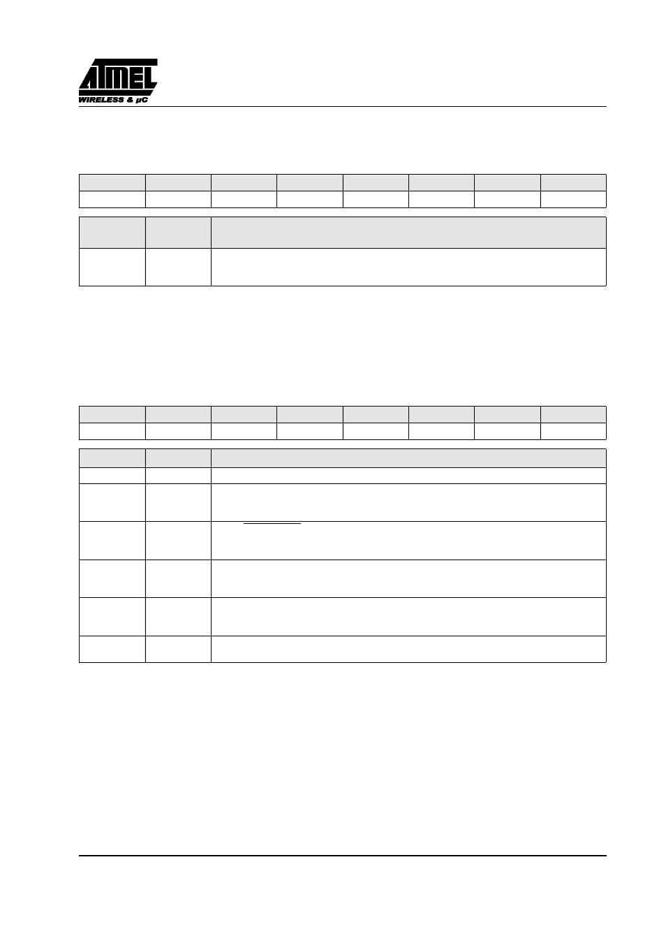
ADCF (S:F6h)
ADC Configuration
Reset Value=0000 0000b
Figure 121. ADCF Register
ADCON (S:F3h)
ADC Control Register
Reset Value=X000 0000b
Figure 122. ADCON Register
7
6
5
4
3
2
1
0
CH 7
CH 6
CH 5
CH 4
CH 3
CH 2
CH 1
CH 0
Bit Number
Bit
Mnemonic
Description
7-0
CH 0:7
Channel Configuration
Set to use P1.x as ADC input.
Clear tu use P1.x as standart I/O port.
7
6
5
4
3
2
1
0
-
PSIDLE
ADEN
ADEOC
ADSST
SCH2
SCH1
SCH0
Bit Number Bit Mnemonic
Description
7
-
6
PSIDLE
Pseudo Idle mode (best precision)
Set to put in idle mode during conversion
Clear to converte without idle mode.
5
ADEN
Enable/Standby Mode
Set to enable ADC
Clear for Standby mode (power dissipation 1 uW).
4
ADEOC
End Of Conversion
Set by hardware when ADC result is ready to be read. This flag can generate an interrupt.
Must be cleared by software.
3
ADSST
Start and Status
Set to start an A/D conversion.
Cleared by hardware after completion of the conversion
2-0
SCH2:0
Selection of channel to convert
see Table 22