Figure 40), Preliminary – Rainbow Electronics T89C51CC02 User Manual
Page 56
56
Rev.A - May 17, 2001
Preliminary
T89C51CC02
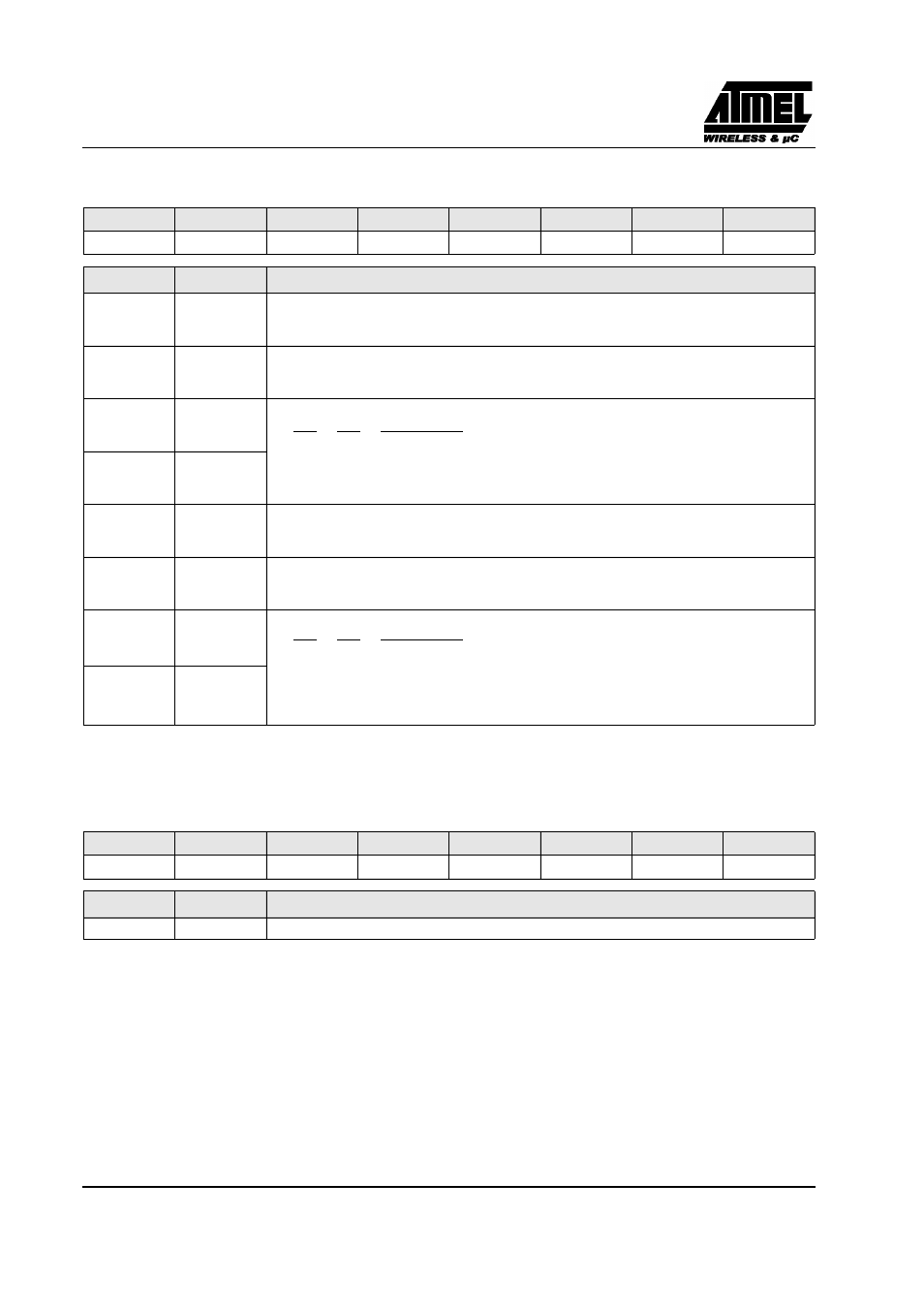
TMOD (S:89h)
Timer/Counter Mode Control Register.
Reset Value= 0000 0000b
Figure 40. TMOD Register
TH0 (S:8Ch)
Timer 0 High Byte Register.
Reset Value= 0000 0000b
Figure 41. TH0 Register
7
6
5
4
3
2
1
0
GATE1
C/T1#
M11
M01
GATE0
C/T0#
M10
M00
Bit Number Bit Mnemonic
Description
7
GATE1
Timer 1 Gating Control Bit
Clear to enable Timer 1 whenever TR1 bit is set.
Set to enable Timer 1 only while INT1# pin is high and TR1 bit is set.
6
C/T1#
Timer 1 Counter/Timer Select Bit
Clear for Timer operation: Timer 1 counts the divided-down system clock.
Set for Counter operation: Timer 1 counts negative transitions on external pin T1.
5
M11
Timer 1 Mode Select Bits
M11
M01
Operating mode
0
0
Mode 0: 8-bit Timer/Counter (TH1) with 5-bit prescaler (TL1).
0
1
Mode 1: 16-bit Timer/Counter.
1
0
Mode 2: 8-bit auto-reload Timer/Counter (TL1). Reloaded from TH1 at overflow.
1
1
Mode 3: Timer 1 halted. Retains count.
4
M01
3
GATE0
Timer 0 Gating Control Bit
Clear to enable Timer 0 whenever TR0 bit is set.
Set to enable Timer/Counter 0 only while INT0# pin is high and TR0 bit is set.
2
C/T0#
Timer 0 Counter/Timer Select Bit
Clear for Timer operation: Timer 0 counts the divided-down system clock.
Set for Counter operation: Timer 0 counts negative transitions on external pin T0.
1
M10
Timer 0 Mode Select Bit
M10
M00
Operating mode
0
0
Mode 0: 8-bit Timer/Counter (TH0) with 5-bit prescaler (TL0).
0
1
Mode 1: 16-bit Timer/Counter.
1
0
Mode 2: 8-bit auto-reload Timer/Counter (TL0). Reloaded from TH0 at overflow.
1
1
Mode 3: TL0 is an 8-bit Timer/Counter.
TH0 is an 8-bit Timer using Timer 1’s TR0 and TF0 bits.
0
M00
7
6
5
4
3
2
1
0
Bit Number Bit Mnemonic
Description
7:0
High Byte of Timer 0.