registers, Preliminary, Registers – Rainbow Electronics T89C51CC02 User Manual
Page 48
48
Rev.A - May 17, 2001
Preliminary
T89C51CC02
11.5. REGISTERS
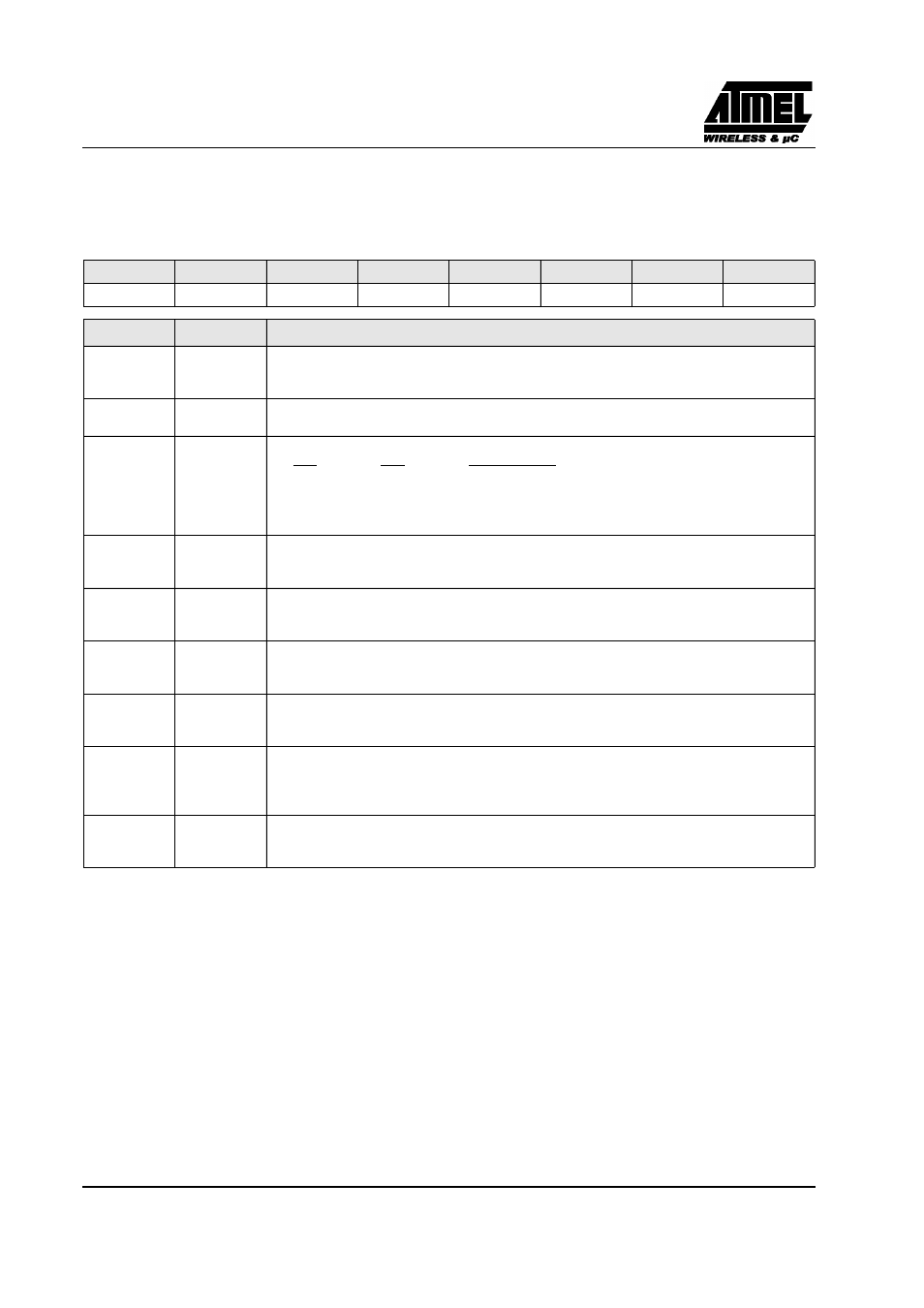
SCON (S:98h)
Serial Control Register
Reset Value = 0000 0000b
Bit addressable
Figure 29. SCON Register
7
6
5
4
3
2
1
0
FE/SM0
SM1
SM2
REN
TB8
RB8
TI
RI
Bit Number Bit Mnemonic
Description
7
FE
Framing Error bit (SMOD0=1)
Clear to reset the error state, not cleared by a valid stop bit.
Set by hardware when an invalid stop bit is detected.
SM0
Serial port Mode bit 0 (SMOD0=0)
Refer to SM1 for serial port mode selection.
6
SM1
Serial port Mode bit 1
SM0
SM1
ModeBaud Rate
0
0
Shift RegisterF
XTAL
/12
0
1
8-bit UARTVariable
1
0
9-bit UARTF
XTAL
/64 or F
XTAL
/32
1
1
9-bit UARTVariable
5
SM2
Serial port Mode 2 bit / Multiprocessor Communication Enable bit
Clear to disable multiprocessor communication feature.
Set to enable multiprocessor communication feature in mode 2 and 3.
4
REN
Reception Enable bit
Clear to disable serial reception.
Set to enable serial reception.
3
TB8
Transmitter Bit 8 / Ninth bit to transmit in modes 2 and 3
Clear to transmit a logic 0 in the 9th bit.
Set to transmit a logic 1 in the 9th bit.
2
RB8
Receiver Bit 8 / Ninth bit received in modes 2 and 3
Cleared by hardware if 9th bit received is a logic 0.
Set by hardware if 9th bit received is a logic 1.
1
TI
Transmit Interrupt flag
Clear to acknowledge interrupt.
Set by hardware at the end of the 8th bit time in mode 0 or at the beginning of the stop bit in the other
modes.
0
RI
Receive Interrupt flag
Clear to acknowledge interrupt.
Set by hardware at the end of the 8th bit time in mode 0, see Figure 27. and Figure 28. in the other modes.