Preliminary – Rainbow Electronics T89C51CC02 User Manual
Page 122
122
Rev.A - May 17, 2001
Preliminary
T89C51CC02
Each of the interrupt sources can be individually enabled or disabled by setting or clearing a bit in the Interrupt
Enable register. This register also contains a global disable bit which must be cleared to disable all the interrupts
at the same time.
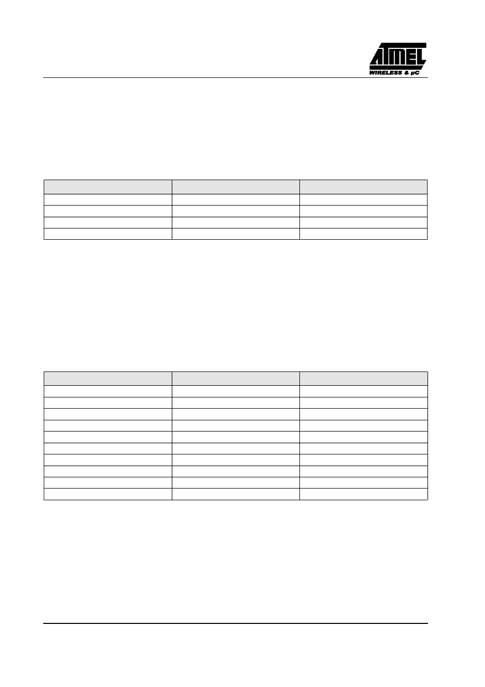
Each interrupt source can also be individually programmed to one of four priority levels by setting or clearing a
bit in the Interrupt Priority registers. The Table below shows the bit values and priority levels associated with each
combination.
Table 23. Priority Level Bit Values
A low-priority interrupt can be interrupted by a high priority interrupt but not by another low-priority interrupt. A
high-priority interrupt cannot be interrupted by any other interrupt source.
If two interrupt requests of different priority levels are received simultaneously, the request of the higher priority
level is serviced. If interrupt requests of the same priority level are received simultaneously, an internal polling
sequence determines which request is serviced. Thus within each priority level there is a second priority structure
determined by the polling sequence, see Table 24.
Table 24. Interrupt priority Within level
IPH.x
IPL.x
Interrupt Level Priority
0
0
0 (Lowest)
0
1
1
1
0
2
1
1
3 (Highest)
Interrupt Name
Interrupt Address Vector
Priority Number
external interrupt (INT0)
0003h
1
Timer0 (TF0)
000Bh
2
external interrupt (INT1)
0013h
3
Timer1 (TF1)
001Bh
4
PCA (CF or CCFn)
0033h
5
UART (RI or TI)
0023h
6
Timer2 (TF2)
002Bh
7
CAN (Txok, Rxok, Err or OvrBuf)
003Bh
8
ADC (ADCI)
0043h
9
CAN Timer Overflow (OVRTIM)
004Bh
10