programmable clock-output, Figure 45. in, Preliminary – Rainbow Electronics T89C51CC02 User Manual
Page 59: Programmable clock-output
Rev.A - May 17, 2001
59
Preliminary
T89C51CC02
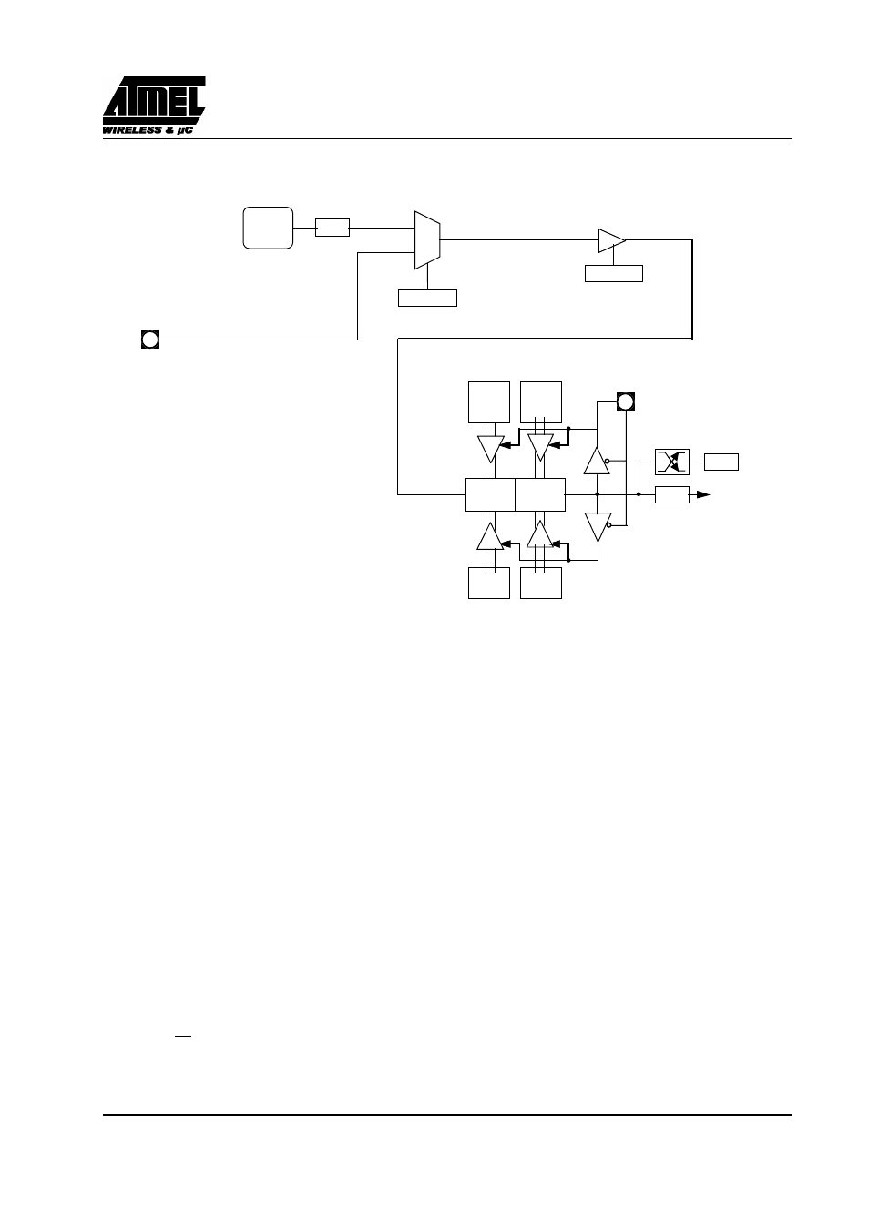
Figure 45. Auto-Reload Mode Up/Down Counter
13.3. Programmable Clock-Output
In clock-out mode, timer 2 operates as a 50%-duty-cycle, programmable clock generator (See Figure 46). The input
clock increments TL2 at frequency F
OSC
/2. The timer repeatedly counts to overflow from a loaded value. At
overflow, the contents of RCAP2H and RCAP2L registers are loaded into TH2 and TL2. In this mode, timer 2
overflows do not generate interrupts. The formula gives the clock-out frequency depending on the system oscillator
frequency and the value in the RCAP2H and RCAP2L registers:
NOTE: X2 bit is located in CKCON register.
In X2 mode, F
OSC
=F
XTAL
. In standard mode, F
OSC
=F
XTAL
/2.
For a 16 MHz system clock, timer 2 has a programmable frequency range of 61 Hz (F
OSC
/2
16)
to 4 MHz (F
OSC
/
4). The generated clock signal is brought out to T2 pin (P1.0).
Timer 2 is programmed for the clock-out mode as follows:
•
Set T2OE bit in T2MOD register.
•
Clear C/T2 bit in T2CON register.
•
Determine the 16-bit reload value from the formula and enter it in RCAP2H/RCAP2L registers.
(DOWN COUNTING RELOAD VALUE)
TF2
T2
EXF2
TH2
(8-bit)
TL2
(
8-bit)
RCAP2H
(8-bit)
RCAP2L
(8-bit)
FFh
(8-bit)
FFh
(
8-bit)
TOGGLE
(UP COUNTING RELOAD VALUE)
TIMER 2
INTERRUPT
:
6
T2CONreg
T2CONreg
T2EX:
1=UP
2=DOWN
0
1
CT/2
T2CON.1
TR2
T2CON.2
FT2
CLOCK
Clock
OutFrequency
–
F
osc
2x2
×
4
65536
RCAP2H
–
RCAP2L
⁄
(
)
Ч
--------------------------------------------------------------------------------------
=