Special function io register – sfior, Atmega8515(l), T1/t0) – Rainbow Electronics ATmega8515L User Manual
Page 93
93
ATmega8515(L)
2512A–AVR–04/02
the edge detector uses sampling, the maximum frequency of an external clock it can
detect is half the sampling frequency (Nyquist sampling theorem). However, due to vari-
ation of the system clock frequency and duty cycle caused by Oscillator source (crystal,
resonator, and capacitors) tolerances, it is recommended that maximum frequency of an
external clock source is less than f
clk_I/O
/2.5.
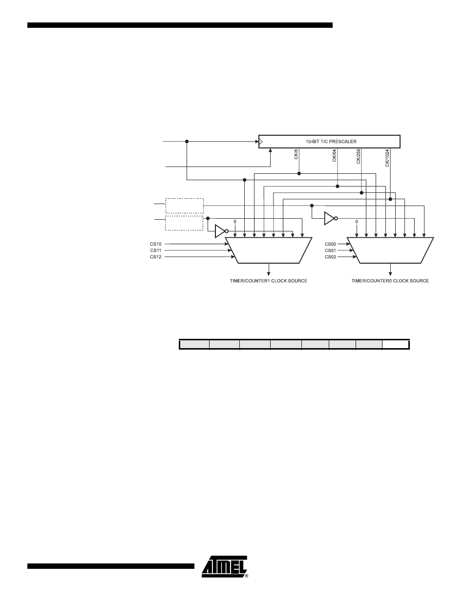
An external clock source can not be prescaled.
Figure 45. Prescaler for Timer/Counter0 and Timer/Counter1
Note:
1. The synchronization logic on the input pins (
T1/T0)
is shown in Figure 44.
Special Function IO Register –
SFIOR
• Bit 0 – PSR10: Prescaler Reset Timer/Counter1 and Timer/Counter0
When this bit is written to one, the Timer/Counter1 and Timer/Counter0 prescaler will be
reset. The bit will be cleared by hardware after the operation is performed. Writing a
zero to this bit will have no effect. Note that Timer/Counter1 and Timer/Counter0 share
the same prescaler and a reset of this prescaler will affect both timers. This bit will
always be read as zero.
PSR10
Clear
clk
T1
clk
T0
T1
T0
clk
I/O
Synchronization
Synchronization
Bit
7
6
5
4
3
2
1
0
–
XMBK
XMM2
XMM1
XMM0
PUD
–
PSR10
SFIOR
Read/Write
R/W
R/W
R/W
R/W
R/W
R/W
R/W
R/W
Initial Value
0
0
0
0
0
0
0
0