External clock, Table 14, Atmega8515(l) – Rainbow Electronics ATmega8515L User Manual
Page 37
37
ATmega8515(L)
2512A–AVR–04/02
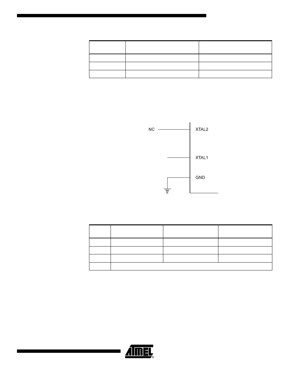
External Clock
To drive the device from an external clock source, XTAL1 should be driven as shown in
Figure 20. To run the device on an external clock, the CKSEL Fuses must be pro-
grammed to “0000”. By programming the CKOPT Fuse, the user can enable an internal
36 pF capacitor between XTAL1 and GND.
Figure 20. External Clock Drive Configuration
When this clock source is selected, start-up times are determined by the SUT Fuses as
shown in Table 15.
Table 14. Internal RC Oscillator Frequency Range.
OSCCAL Value
Min Frequency in Percentage of
Nominal Frequency
Max Frequency in Percentage of
Nominal Frequency
$00
50%
100%
$7F
75%
150%
$FF
100%
200%
Table 15. Start-up Times for the External Clock Selection
SUT1..0
Start-up Time from
Power-down
Additional Delay from
Reset (V
CC
= 5.0V)
Recommended Usage
00
6 CK
–
BOD enabled
01
6 CK
4.1 ms
Fast rising power
10
6 CK
65 ms
Slowly rising power
11
Reserved
EXTERNAL
CLOCK
SIGNAL
- MAX5151 (16 pages)
- MAXQ3108 (64 pages)
- MAX5661 (39 pages)
- MAX6691 (7 pages)
- MAX5362 (12 pages)
- ADC10158 (26 pages)
- MAX8922L (14 pages)
- MAX8596Z (8 pages)
- MAX7491 (18 pages)
- MAX15040 (15 pages)
- MAX5177 (16 pages)
- ADC08138 (22 pages)
- MAX5961 (42 pages)
- T89C51RD2 (86 pages)
- MAX16055 (9 pages)
- MAX6659 (17 pages)
- ADC0820 (20 pages)
- MAX6678 (19 pages)
- MAX8884Z (15 pages)
- MAX16915 (9 pages)
- MAX8620 (18 pages)
- MAX5144 (12 pages)
- MAX6670 (8 pages)
- MAX8760 (39 pages)
- W78C32C (14 pages)
- MX7533 (8 pages)
- MAX8727 (13 pages)
- MAX9053 (15 pages)
- W78C54 (16 pages)
- MAX8614B (15 pages)
- W90N740 (219 pages)
- MAX6626 (13 pages)
- ADC10738 (30 pages)
- MAX17000 (31 pages)
- MAX5051 (21 pages)
- MAXQ1004 (18 pages)
- MAX6871 (51 pages)
- MX7847 (12 pages)
- MAX6608 (6 pages)
- MAX17083 (15 pages)
- MAX6641 (17 pages)
- MAX5251 (16 pages)
- MAX6338 (8 pages)
- MAX6690 (16 pages)
- MAX8668 (18 pages)