Using the external memory interface, Figure 11, Atmega8515(l) – Rainbow Electronics ATmega8515L User Manual
Page 23
23
ATmega8515(L)
2512A–AVR–04/02
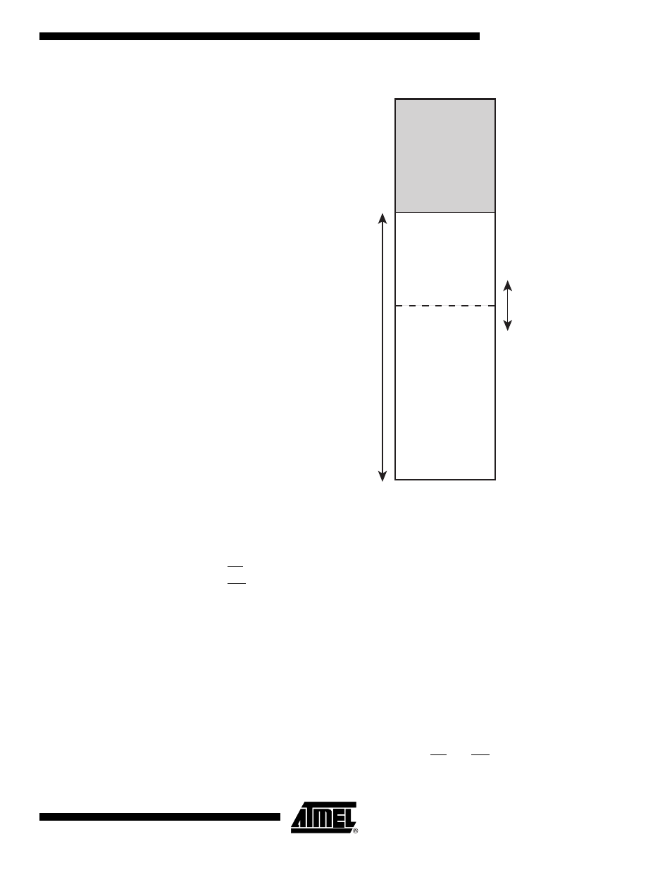
Figure 11. External Memory with Sector Select
Using the External Memory
Interface
The interface consists of:
•
AD7:0: Multiplexed low-order address bus and data bus
•
A15:8: High-order address bus (configurable number of bits)
•
ALE: Address latch enable
•
RD: Read strobe
•
WR: Write strobe
The control bits for the External Memory Interface are located in three registers, the
MCU Control Register – MCUCR, the Extended MCU Control Register – EMCUCR, and
the Special Function IO Register – SFIOR.
When the XMEM interface is enabled, it will override the settings in the data direction
registers corresponding to the ports dedicated to the interface. For details about this port
override, see the alternate functions in section “I/O Ports” on page 56. The XMEM inter-
face will auto-detect whether an access is internal or external. If the access is external,
the XMEM interface will output address, data, and the control signals on the ports
according to Figure 13 (this figure shows the wave forms without wait states). When
ALE goes from high to low, there is a valid address on AD7:0. ALE is low during a data
transfer. When the XMEM interface is enabled, also an internal access will cause activ-
ity on address-, data-, and ALE ports, but the RD and WR strobes will not toggle during
internal access. When the External Memory Interface is disabled, the normal pin and
0x0000
0x25F
External Memory
(0-64K x 8)
0xFFFF
Internal Memory
SRL[2..0]
SRW11
SRW10
SRW01
SRW00
Lower Sector
Upper Sector
0x260