Atmega8515(l) – Rainbow Electronics ATmega8515L User Manual
Page 43
43
ATmega8515(L)
2512A–AVR–04/02
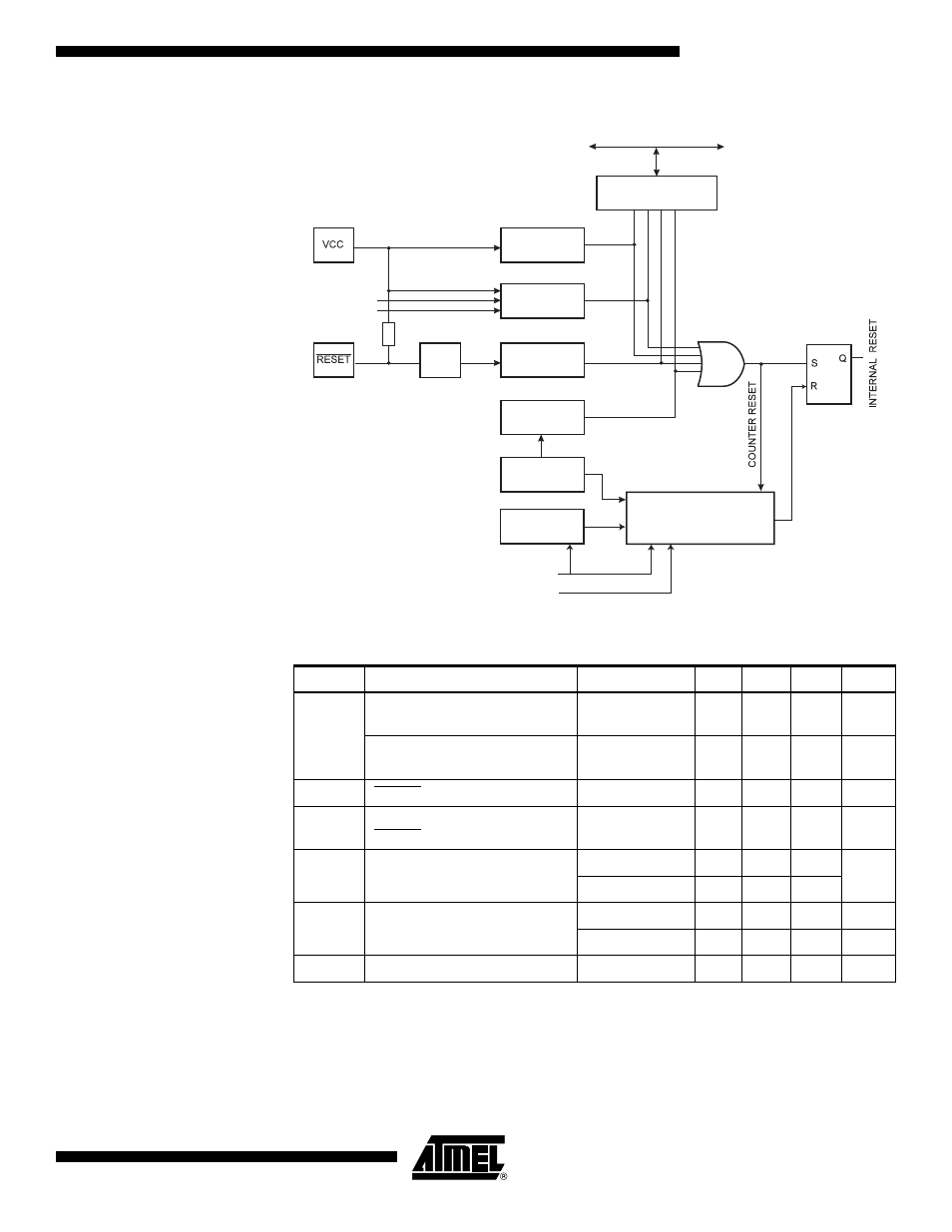
Figure 21. Reset Logic
Note:
1. The Power-on Reset will not work unless the supply voltage has been below V
POT
(falling)
Table 18. Reset Characteristics
Symbol
Parameter
Condition
Min
Typ
Max
Units
V
POT
Power-on Reset Threshold
Voltage (rising)
1.4
2.3
V
Power-on Reset Threshold
Voltage (falling)
1.3
2.3
V
V
RST
RESET Pin Threshold Voltage
0.1
0.9
V
CC
t
RST
Minimum pulse width on
RESET Pin
50
ns
V
BOT
Brown-out Reset Threshold
Voltage
BODLEVEL = 1
2.5
2.7
3.2
V
BODLEVEL = 0
3.7
4.0
4.2
t
BOD
Minimum low voltage period for
Brown-out Detection
BODLEVEL = 1
2
µs
BODLEVEL = 0
2
µs
V
HYST
Brown-out Detector hysteresis
130
mV
MCU Control and Status
Register (MCUCSR)
Brown-out
Reset Circuit
BODEN
BODLEVEL
Delay Counters
CKSEL[3:0]
CK
TIMEOUT
WDRF
BORF
EXTRF
PORF
DATA BUS
Clock
Generator
Spike
Filter
Pull-up Resistor
Watchdog
Oscillator
SUT[1:0]
Power-on
Reset Circuit
Reset Circuit
Watchdog
Timer
- MAX5151 (16 pages)
- MAXQ3108 (64 pages)
- MAX5661 (39 pages)
- MAX6691 (7 pages)
- MAX5362 (12 pages)
- ADC10158 (26 pages)
- MAX8922L (14 pages)
- MAX8596Z (8 pages)
- MAX7491 (18 pages)
- MAX15040 (15 pages)
- MAX5177 (16 pages)
- ADC08138 (22 pages)
- MAX5961 (42 pages)
- T89C51RD2 (86 pages)
- MAX16055 (9 pages)
- MAX6659 (17 pages)
- ADC0820 (20 pages)
- MAX6678 (19 pages)
- MAX8884Z (15 pages)
- MAX16915 (9 pages)
- MAX8620 (18 pages)
- MAX5144 (12 pages)
- MAX6670 (8 pages)
- MAX8760 (39 pages)
- W78C32C (14 pages)
- MX7533 (8 pages)
- MAX8727 (13 pages)
- MAX9053 (15 pages)
- W78C54 (16 pages)
- MAX8614B (15 pages)
- W90N740 (219 pages)
- MAX6626 (13 pages)
- ADC10738 (30 pages)
- MAX17000 (31 pages)
- MAX5051 (21 pages)
- MAXQ1004 (18 pages)
- MAX6871 (51 pages)
- MX7847 (12 pages)
- MAX6608 (6 pages)
- MAX17083 (15 pages)
- MAX6641 (17 pages)
- MAX5251 (16 pages)
- MAX6338 (8 pages)
- MAX6690 (16 pages)
- MAX8668 (18 pages)