Figure 19 – M&C TechGroup SP2000H_DIL_BR Operator's manual User Manual
Page 33
33
Gas sampling and gas conditioning technology
2-1.1.7-ME
W A R N I N G !
The Swagelok
®
fittings must be carefully tightened to avoid damag-
ing the internal components!
16.3.3
CHANGE OF THE GRAPHITE PACKING AT THE BYPASS INJECTOR (320°C
VERSION)
When changing the injector the packing (320°C version) must be changed as well.
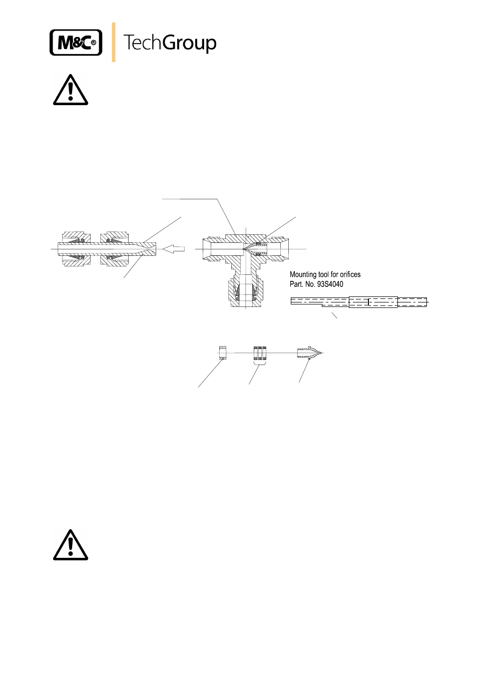
Figure 16 shows the bypass injector unit of a 320°C version.
Thrust collar
Nozzle
Graphite rings
Part No.: 93S4003
Injector complete, DIL-H320-BR
Mounting tool
Part No.: 93 S 4040
Jet pipe
Bypass-T
Pos.1:
Packing for injector nozzle
consisting of 3 graphite rings
4/
6
– 1,5mm thickness
Part NO.: 93 S 4010
Figure 19
Bypass Injector unit with graphite packing (320°C version)
We recommend the following steps:
Unscrew the jet pipe (pos. 2) from the Bypass-T;
Push out the injector nozzle from the opposite side (tool pos. 3);
Remove the thrust collar and the graphite rings;
Push 3 new rings on the nozzle;
Put on the thrust collar;
Push the injector into the T up to the block and press it tightly. Use the mounting tool.
W A R N I N G !
The Swagelok
®
fittings must be carefully tightened to avoid damag-
ing the internal components!