Figure 17, Bypass-t with injector and o-ring (180°c version) – M&C TechGroup SP2000H_DIL_BR Operator's manual User Manual
Page 31
31
Gas sampling and gas conditioning technology
2-1.1.7-ME
Please change the packing as follows:
Loosen union nut 3 and remove the jet pipe;
Loosen nut 4 and remove the dilution tube connection;
Push out the injector with the tool (Pos. 3) from the opposite side (jet pipe);
Remove the thrust collar from the nozzle;
Remove the graphite rings;
Push on the nozzle and the 3 new graphite rings;
Replace the thrust collar;
Re-install the injector with the tool. Push it up to block and press it tightly.
W A R N I N G !
The Swagelok
®
fittings must be carefully tightened to avoid damag-
ing the internal components!
16.3
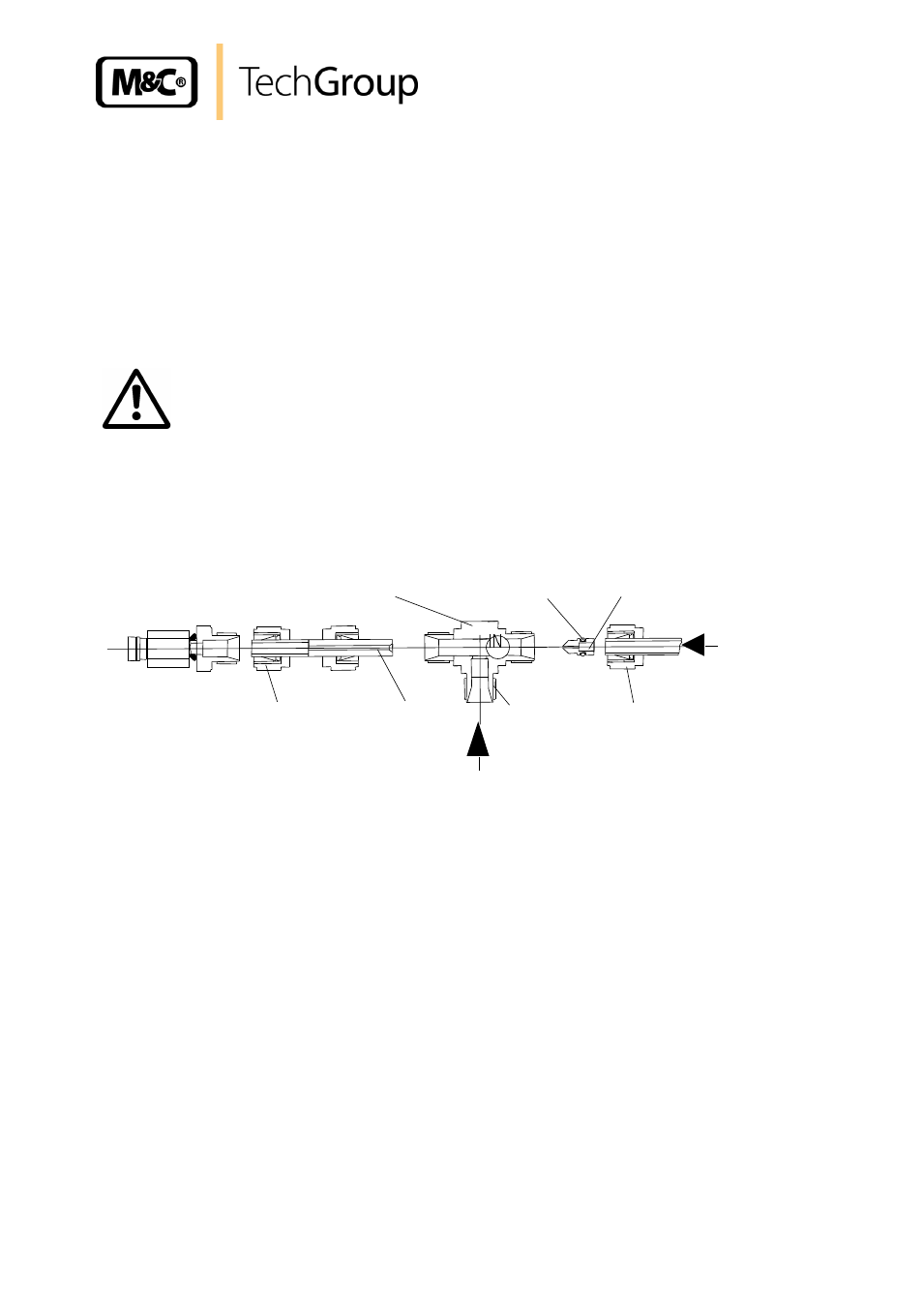
REMOVING THE BYPASS-T USING OPTION ..B/..BR (180°C VERSION)
For maintenance and cleaning the Bypass-T can be dismantled completely. The figure below shows
the scheme of the Bypass-T.
Injector nozzle
O-ring
Bypass-T
Jet pipe
Union nut 2
Nut 1
Nut 3
Sample gas
Dilution gas
Figure 17
Bypass-T with Injector and o-ring (180°C version)
Dismantle the Bypass-T as follows:
Remove probe insulating cover (see 16.1);
Remove all pipe connections on Bypass-T. These are:
-
Bypass inlet union nut 1
-
union nut 2 (sample outlet side)
-
union nut 3 (sample inlet).
The Bypass-T is now ready for further maintenance and repair.