Figure 14 – M&C TechGroup SP2000H_DIL_BR Operator's manual User Manual
Page 28
28
Gas sampling and gas conditioning technology
2-1.1.7-ME
16.2.1
CHANGE AND CLEANING OF THE CRITICAL ORIFICE (180°C VERSION)
W A R N I N G !
Do not clean the critical orifice mechanically.
Cleaning should take place in an ultrasonic bath!
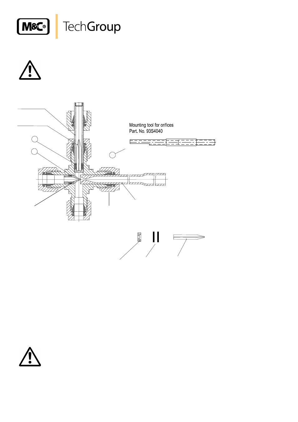
Figure 14 shows the position of the orifice in the crosspiece and the o-ring seals (180°C version).
Jet pipe
2
1
Orifice
Sucking pipe
Pos. 2:
Sealing set for critical orifice
consisting of 2 o-rings
Part No.: 93 S 4009
Orifice
Seat
O-rings
Mounting tool
Part No.: 93S4040
3
Nut 3
Injector
Figure 14
Crosspiece with critical orifice and o-ring seals (180°C version)
Please dismantle as follows:
Loosen union nut 3 and remove the jet pipe;
Push the injector out with the mounting tool (pos. 3, Fig. 14). Carry it out from the opposite
side;
Push the critical orifice, orifice seat and o-rings carefully out of the crosspiece (with the tool
from the opposite side) ;
Check the o-rings and change them if necessary;
Re-fit the new respectively cleaned orifice into the o-rings (180°C-Version) up to block.
Re-install the dilution unit in the opposite way.
W A R N I N G !
The Swagelok
®
fittings must be carefully tightened to avoid damag-
ing the internal components. Tightening too far will damage the
cross.
Use a mating gauge to make sure that the fittings are not too tight.
If a fitting is believed to be leaking, do not tighten the fitting to re-
move the leak. Disassemble the piece completely and reassemble it
making sure that the nut is not tightened too far.