Figure 9, Extract from an injector data sheet, Figure 10 – M&C TechGroup SP2000H_DIL_BR Operator's manual User Manual
Page 22: Bypass injector data sheet
22
Gas sampling and gas conditioning technology
2-1.1.7-ME
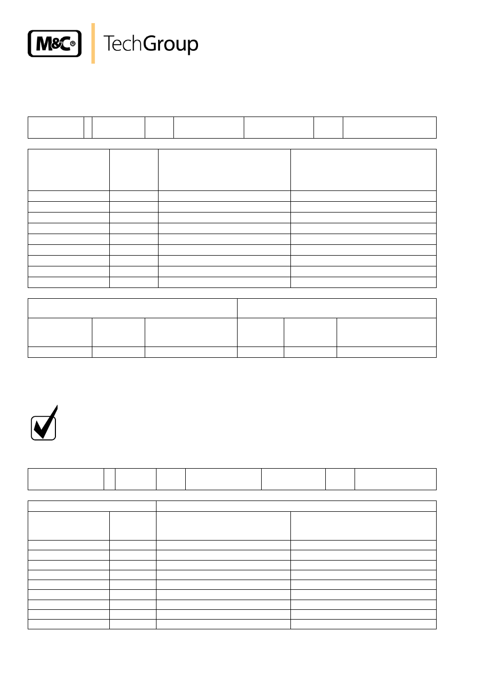
An extract from an injector data sheet is shown below.
Injektor-Datenblatt / Injector data sheet
Injektortyp
I
Injektor-Nr.
689
Für Sonden-Nr.
8652/222835
Typ
SP2000-H/DIL/BR
Injector type
Injector No.
For probe No.
Type
Betriebsdruck
Operating pres-
sure
[bar]
Durchfluss
Flow
[l/h]
Unterdruck ohne kritische Düse
Vacuum without critical orifice
[bar]
Unterdruck mit kritischer Düse
Vacuum with critical orifice 5,1l/h
[bar]
2,4
415
-0,62
-0,61
2,6
435
-0,65
-0,64
2,8
460
-0,68
-0,67
3,0
490
-0,80
-0,77
3,2
510
-0,79
-0,77
3,4
535
-0,79
-0,77
3,6
560
-0,78
-0,76
3,8
585
-0,77
-0,76
4,0
605
-0,77
-0,75
Überprüfung des Verdünnungsfaktors
Check of the dilution ratio
Messgasdruck atmosphärisch
Sample gas pressure atmospheric
Kritische Düse
Critical nozzle
Verd.gas
Dilution gas
Verdünnungsgasdruck
Dilution gas pressure
Messgas
Sample
Verdünnung
Dilution
Messwert d. verd. Gases
Meas. value of the dil.
gas
5,1 l/h
100% N
2
3,1 bar
100% O
2
100:1
1,0 % O
2
Figure 9
Extract from an injector data sheet
For the operation of an installed bypass injector, the necessary pressure must be set on the pressure
regulator provided (on left next to precision pressure regulator).
N O T E !
The gas pressure must be higher than 0.7 bar, as the vacuum valve
mounted on the probe has an opening pressure of 0. 7 bar.
When using the control panel, the respective ball valve for the test
gas supply must be opened and the flow rate set on the flow meter.
Bypass- Injektor
I
Ser.-Nr.
526
Für Sonden-Nr.
8652/222835
Typ
SP2000-H/DIL/BR
Bypass injector
Ser. No.
For probe No.
Type
Bypassgas / Bypass gas
Prozessgas / Sample gas
Betriebsdruck
Operating pressure
[bar]
Durchfluss
Flow
[l/h]
Ansaugvolumenstrom bei 1bar
abs. Suction flow at 1bar abs.
[l/h]
Ansaugvolumenstrom bei 0,9bar abs.
Suction flow at 0,9bar abs.
[l/h]
0,5
110
45
-
1,0
155
115
-
1,5
190
200
65
2,0
235
250
135
2,5
270
300
200
3,0
310
350
250
3,5
355
370
270
4,0
395
390
305
4,5
430
425
350
Figure 10
Bypass injector data sheet