Types with internal capillary tube hermostat, Types with external temperature controller – M&C TechGroup SP2000H_DIL_BR Operator's manual User Manual
Page 20
20
Gas sampling and gas conditioning technology
2-1.1.7-ME
13.5.1
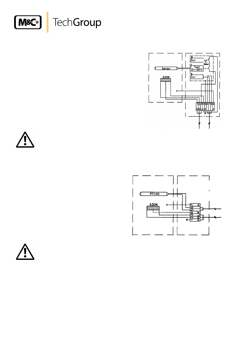
TYPES WITH INTERNAL CAPILLARY TUBE HERMOSTAT
Remove cover of connection box. The electrical wiring
diagram is located in the cover.
Insert mains cable (min. 3x1.5mm
2
) through cable gland
and connect to appropriate terminals.
Insert signal cable (under-temperature alarm) through ca-
ble gland and connect to appropriate terminals (the contact
T
u
shows the alarm event).
Screw cover back in place.
W A R N I N G !
For connecting use temperature resistant cable!
13.5.2
TYPES WITH EXTERNAL TEMPERATURE CONTROLLER
Remove cover of connection box. The electrical
wiring diagram is located in the cover.
Insert mains cable (min. 3x1.5mm
2
) through cable
gland and connect to appropriate terminals.
Insert temperature sensor cable through cable
gland and connect to appropriate terminals.
Screw cover back in place.
W A R N I N G !
Use corresponding compensating lines with thermocouples !
Power 230V 50Hz
or 115V 60Hz
Alarm output
1
2
1
2
+30°C
-30°C
Power 230V 50Hz
or 115V 60Hz
PT100 or
thermocouple
1
2
1
2