Dismantling the dilution cross, Figure 13, Exploded drawing of dilution unit – M&C TechGroup SP2000H_DIL_BR Operator's manual User Manual
Page 27
27
Gas sampling and gas conditioning technology
2-1.1.7-ME
16.2
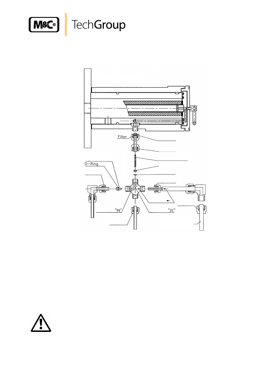
DISMANTLING THE DILUTION CROSS
Figure 11 shows an exploded drawing of the dilution unit.
Nut 1
Nut 2
Nut 3
Nut 4
Nut 5
Nut 6
Critical orifice
Mark
Injector
Mark
Mark
Tube sample gas
out
Block
180°C Version
O-rings
Figure 13
Exploded drawing of dilution unit
The following step-by-step procedure is recommended:
Remove probe insulating cover (see 16.1).
Loosen knurled screw for fixing heat conducting plates.
Remove heat conducting plates.
Remove all pipe connections on dilution unit (crosspiece). These are:
- vacuum pressure gauge nut 6
- dilution gas inlet nut 4
- sample gas outlet nut 5 (remove sample gas out pipe at upper elbow union. Do not remove
pipe connected to crosspiece)
- nut 1.
W A R N I N G !
Do not remove nut 2 until the dilution cross is removed from the
probe or the orifice will be broken !
The dilution cross is now ready for further maintenance and repair work.
- SP10 Operator's manual (14 pages)
- N9 KP18 Operator's manual (21 pages)
- SP2000_20SS 150 Data sheet (3 pages)
- SP3100 Data sheet (6 pages)
- PSP4000-H _C _T Data sheet (4 pages)
- SP2200-H_C_I_BB_F Data sheet (2 pages)
- SP35-H... for gas sample probe SP2000-H... Data sheet (2 pages)
- FP-BF Data sheet (2 pages)
- SP3200 Operator's manual (28 pages)
- FPF-0,1 Operator's manual (2 pages)
- PSS-10_1 Operator's manual (23 pages)
- CSS-V2 Data sheet (3 pages)
- PMA 50 EEX Operator's manual (48 pages)
- MP30 Operator's manual (18 pages)
- SP2600-H_C_I_BB_F_0,1GF190 Data sheet (3 pages)
- SR25.1_Ex Operator's manual (22 pages)
- PMA 10S Operator's manual (27 pages)
- CSS-M_W Data sheet (3 pages)
- PAS-500 Operator's manual (20 pages)
- SP2000H320_DIL... Data sheet (3 pages)
- SP3200 Data sheet (6 pages)
- FA-1_2_3,bi Operator's manual (24 pages)
- SR25 Data sheet (2 pages)
- SP3000 Data sheet (4 pages)
- PAS Series Data sheet (2 pages)
- CG Series Data sheet (2 pages)
- ECP 20-2 Data sheet (3 pages)
- MP30-EX Data sheet (2 pages)
- PSP4000-H_C_T Operator's manual (24 pages)
- DIL-U Data sheet (2 pages)
- ADS-So Data sheet (2 pages)
- VC-2-SL Operator's manual (18 pages)
- ECM-ExII Operator's manual (39 pages)
- MP12 Operator's manual (17 pages)
- FPF+ Data sheet (2 pages)
- KS 2.Ex Operator's manual (17 pages)
- PMA 50 EEX Data sheet (3 pages)
- PMA 10S Data sheet (3 pages)
- Gas Sample Probes Series SP Data sheet (2 pages)
- BA-C Operator's manual (16 pages)
- MV3_2-H Series Operator's manual (18 pages)
- VC-2-SL Data sheet (3 pages)
- FM-200K-H_FA Operator's manual (16 pages)
- SP 30-H.._EX2 Operator's manual (16 pages)
- SP2006-H280_DIL Operator's manual (35 pages)