Figure 4, Installation set and control panel, Figure 4 installation set and control panel – M&C TechGroup SP2000H_DIL_BR Operator's manual User Manual
Page 11
11
Gas sampling and gas conditioning technology
2-1.1.7-ME
The probe can also be provided with an optional hand-operated, heated shut-off ball valve in the inlet -
VA (see Fig. 2) for the purpose of sealing off the filter space from the sampling process during filter
replacement. Another option is the second sample outlet for undiluted gas (..2x, see Fig.1)
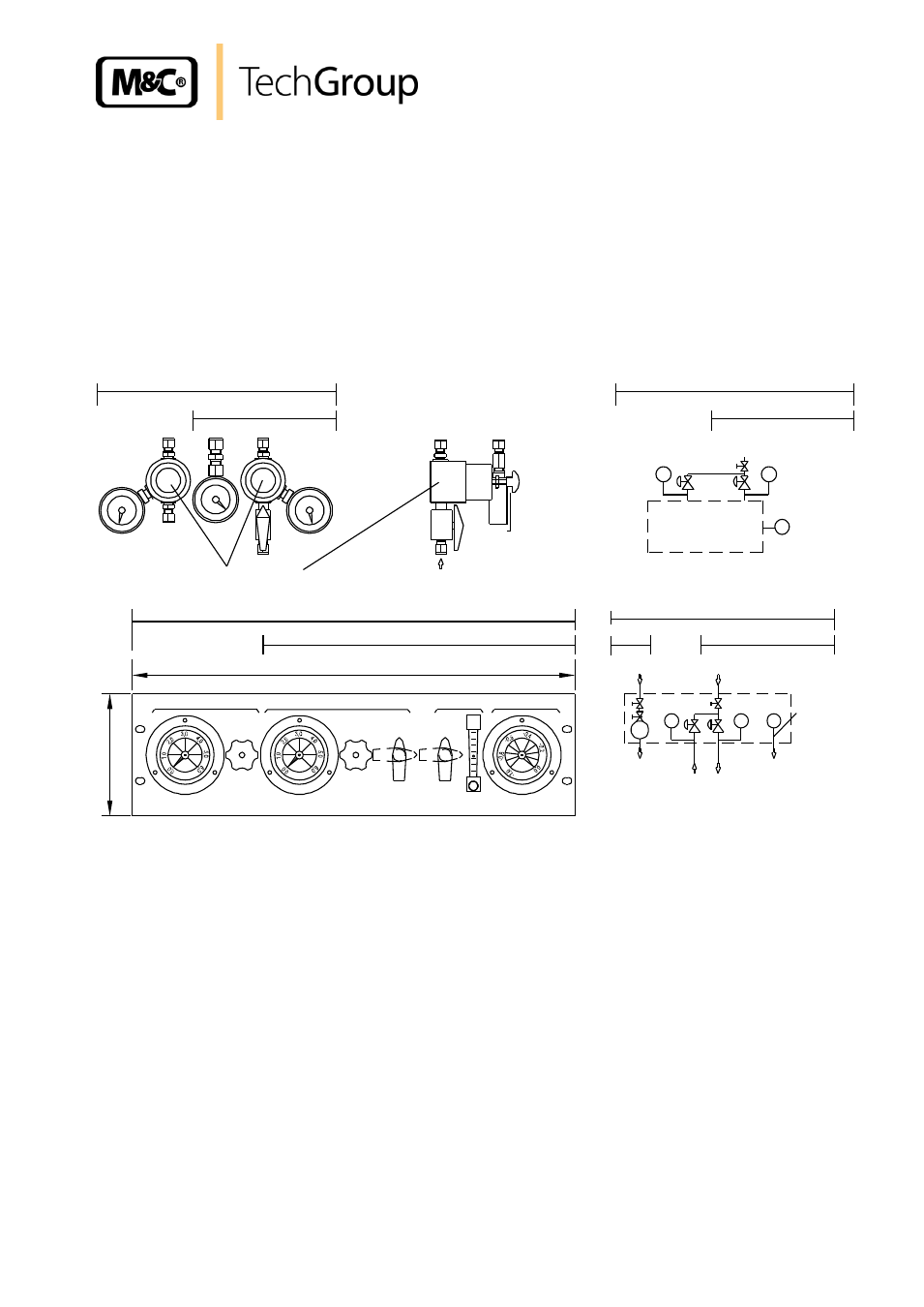
A precision pressure regulator with pressure gauge serves for adjustment of the necessary dilution
gas supply pressure. The function of the dilution injector is monitored via a vacuum pressure gauge.
The pressure regulator and pressure gauge necessary for the dilution function must be ordered sepa-
rately. Set -A is mounted directly on the probe. Control panel -S is designed for external installation
and is additionally provided with a shut-off valve and flow meter for test gas volume adjustment. The
options -A1 and -S1 include an additional pressure regulator for the bypass injector
–B or bypass
injector with process return
–BR (see Fig. 1).
Pressure regulator
-A
-A1
-A1
-A
-1...0 bar
measuring point
SP2000H/DIL...
0-6bar
PI
Dilution gas
0-6bar
PI
PI
Underpressure
Bypass
Dilution gas
Vacuum pressure
-1...0 bar
1
32
(
3
H
E
)
19" (84TE)
SP2000H/DIL...
-S1
-S
-S
Open
Test gas
Inj.-low pressure
Open
Dilution gas
Bypass-Injector
-S
-S1
Bypass gas
measurement
PI
0-6 bar
1
5-
1
50
N
l/
h
-1..0 bar
0-6 bar
FI
PI
PI
Low pressure
Test gas
Dilution gas/Bypass
Dilution gas
Figure 4
Installation set and control panel
The dilution probe can be used for standard dilution factors from 10:1 to 500:1 (Injector I). Higher dilu-
tion rates in a ratio of 50:1 to 2000:1 are possible (Injector II).
Where a correspondingly small sample gas volume is taken from the process with large dilution fac-
tors, an optional heated bypass injector that is integrated directly upstream of the dilution part is avail-
able for reducing the response time in atmospheric respectively small vacuum operation. The bypass
option is available without gas return
–B or with gas return to the process –BR . In vacuum op-
eration, a bypass needle valve
–BV serves for bypass volume adjustment (see Fig. 3).
The dilution unit is designed for problem-free operation independent of the process temperature and
process pressure (see technical data) as well as for easy maintenance.