Technical data, 8technical data – M&C TechGroup SP2000H_DIL_BR Operator's manual User Manual
Page 13
13
Gas sampling and gas conditioning technology
2-1.1.7-ME
8
TECHNICAL DATA
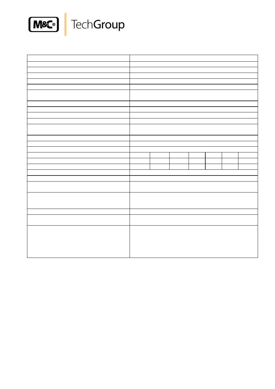
Technical data SP series
®
Dilution probe version SP2000H/DIL ..
Weather protective cover
Yes
Electrical connection
Terminals; max. 4 mm²
Degree of protection of terminal box
IP54
EN60529
Mains supply
230V 50/60Hz, 800W
or
115V 60Hz, 800W
(fuse 10A)
Material of medium contacted parts
Stainless steel 1.4571, 1.4404, quartz glass, FPM, graphite
Ambient temperature
Thermostat: +5°C to 60°C
PT100, thermocouple: +5°C to 80°C
Operating temperature
0-180°C* alternatively 0-320°C
Ready
after 2 h
Temperature status alarm
/
30°C to T
NOMINAL
*
Alarm contact rating
250V 3A AC, 0:25A DC
Sample gas outlet connection
1/4"-NPT internal, for max. 10mm pipe union
for version /H320 = pipe union ø
i
6mm*
Test gas back-flushing connection
for version /R pipe 6mm o.d.*
Filter space volume
120 ml
Weight
about 20 kg
Orifice type
a
b
c
d
e
f
g
Dilution factors
1)
500:1
200:1
100:1
50:1
30*:1
20:1
10:1
Sample gas volume [Nl/hr]
2)
1.4
2.7
5.5
11
19*
28
55
Dilution factor adjustment range
with dilution gas supply pressure setting -5% - +30%
3)
Dilution gas volume injector version I or II
I: 480-600 Nl/hr*, optional II: 1800
–3000 Nl/hr
Dilution gas supply pressure upstream of pres-
sure regulator
Min. 4.5 bar, max. 16 bar
Bypass injector/B/BR:
Supply pressure
– gas consumption – sample
gas volume
about 2 bar : Propellant ca. 300 l/hr : Sample gas about 150
l/hr
Process pressure
0.9 to 2 bar abs. at constant pressure
Influence of process temperature variations
No influence due to operation independent of process tem-
perature
Influence of pressure change
Influence negligible at pressure changes
≤ 200mbar other-
wise proportional to pressure changes.
Calibration of probe must be performed under process con-
ditions or pressure correction must be implemented. Op-
tional connection for pressure measurement / compensation
1/4“ NPT i.
* Standard, specify other values when ordering, intermediate values can also be specified.
1)
Values with injector I (higher dilution rates with injector II possible),
2)
at about 3 bar (downstream of supply pressure regulator) dilution gas,
3)
-
5% however, not for orifice “g”