Connection of supply tubes for dilution bypass gas, Figure 8, Sp2000h/dil/b with control panel dil/s1 – M&C TechGroup SP2000H_DIL_BR Operator's manual User Manual
Page 18
18
Gas sampling and gas conditioning technology
2-1.1.7-ME
Option
–A/A1
When ordering option
–A or -A1, the sets, consisting of pressure regulators and pressure gauges, are
mounted directly on the probe (see Fig.2). Connection of the sample pipe takes place at the elbow
union of the probe (see above).
Option
–S/S1
For option
–S or - S1, the necessary pressure regulators, pressure gauge, shut-off valves and flow
meter are installed externally in a 19“ control panel (see Fig. 4). Connection of the sample or supply
pipes to the probe and downstream analyser system must be established by the customer. Appropri-
ately marked connections are provided at the rear of the 19“ unit.
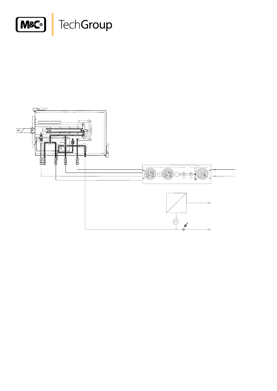
Test gas
njector-vacuum
Dilution gas
Bypass injector
Open
Open
500 l/h
Check valve
Calibration gas
Dilution gas
Vacuum pressure gauge
Bypass
Control panel DIl/S1
Dilution gas
Cal gas
Sample out
Bypass
Analyser
Figure 8
SP2000H/DIL/B with control panel DIL/S1
13.3
CONNECTION OF SUPPLY TUBES FOR DILUTION BYPASS GAS
Available for connection of the supply tubes are probe-sided tube unions with the dimension
DN4/6mm (1/4“
o
for 115V version). The tube unions are located outside the probe cover and can
be connected without disassembly.
When using option
–A (only dilution gas) or –A1 (dilution and bypass gas), the supply tubes are con-
nected to the unions of the precision pressure regulator.
When using the 19“ control panels, corresponding connections for the supply gases are provided at
the rear of the unit.
Back pressure max. 1,2 bar abs.