Operating principle of the controller 70304, Parameter of the user level with factory setting, Figure 12 – M&C TechGroup CSS Series Operator's manual User Manual
Page 24: Display/control elements
24
Gas sampling and gas conditioning technology
4-1.1-ME
11
DESCRIPTION OF THE OPTIONAL TEMPERATURE CONTROLLER 70304 FOR
HEATED SAMPLE LINES
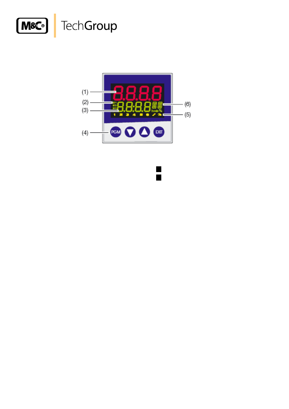
(1)
Actual value display
red, 10mm high, 4 digits
(4)
PGM-key in order to select parameters
in order to change values
in order to change values
Exit-key in order to leave the levels
(2)
Active Setpoint
Factory setting SP1
(5)
Indication
yellow for
- Switch status of binaryoutputs 1
– 6
(display lights up = on)
- ramp/programm function is active
- manual operation is active
(3)
Setpoint
Four digit, green; decimal place is configur-
able;
Also used for operator prompting (display of
parameter and level symbols)
(6)
16-segment display for the unit °C / °F
factory setting °C
Figure 12 Display/control elements
12
OPERATING PRINCIPLE OF THE CONTROLLER 70304
Operating and programming of the controller takes place on two levels. On the first level for normal
operation, alarms can be resetted or in case of startup a control circuit, self-optimising is activated.
Underneath there is the user level. All important adjustments of the controller are combined on the
user level and can be changed after removing the level inhibit.
12.1 PARAMETER OF THE USER LEVEL WITH FACTORY SETTING
Setpoint SP, factory setting = 180°C
Max. low temperature difference to the setpoint Lo-t, factory setting = 10°C. In case of falling
below, an alarm signal takes place