Figure 3 – M&C TechGroup CSS Series Operator's manual User Manual
Page 13
13
Gas sampling and gas conditioning technology
4-1.1-ME
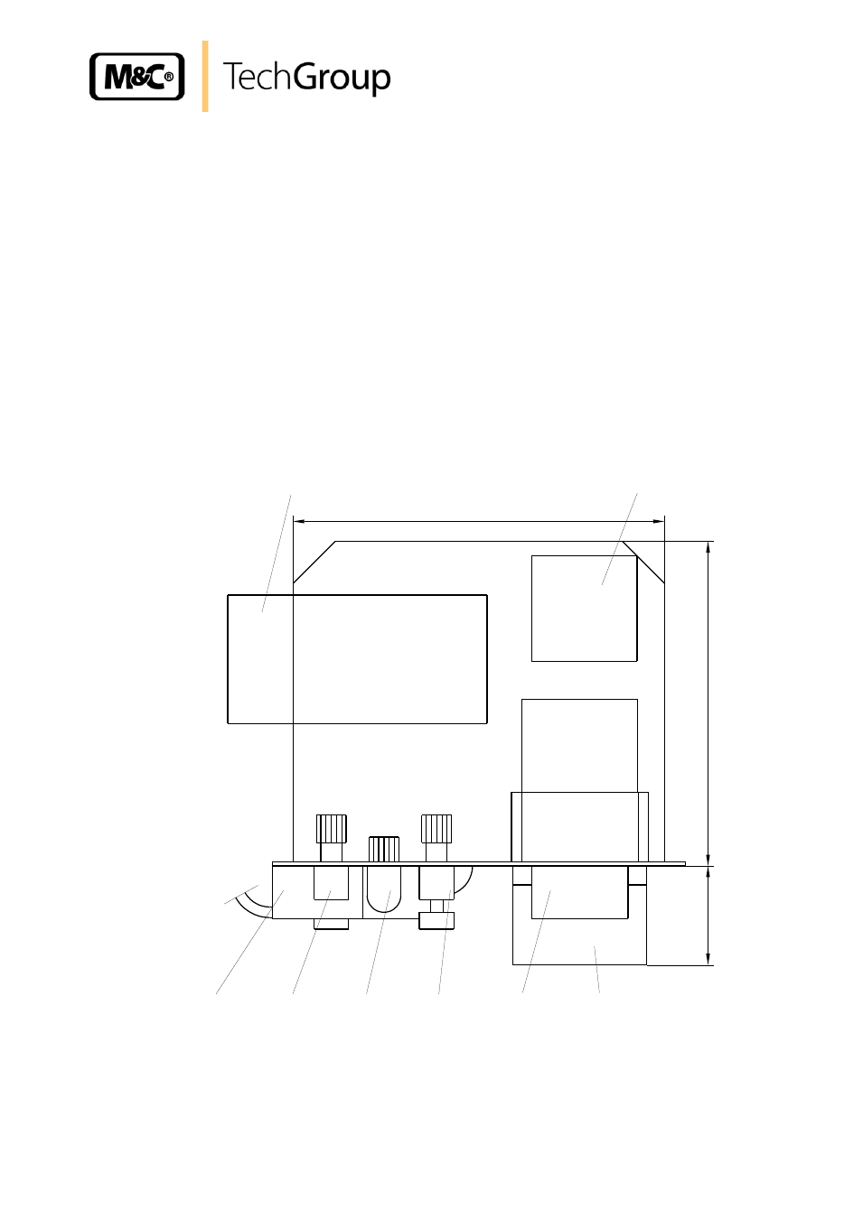
All of the maintenance components are mounted on the flow components sub panel (1.2) (s. Fig. 1
and 3) and are easily accessed by removing front panel mounting screws. These are:
(1.2.1) Gas-Filter FPF-0,1GF;
(1.2.2) Peristaltic pump SR25.1;
(1.2.3) Liquid-Alarm-Sensor LA1 with Flow-Chamber LS;
(1.2.4) Flow-Meter 1 FM40, measuring range 7-70l or 25-250l**
(1.2.5) Optical bi stable Flow-Alarm-Sensor FA-1,bi;
(1.2.6) Flow-Meter 2 FM40, measuring range 7-70l or 25-250l**;
(1.2.7) Gas Pump N3 KPE or N9 KPE**;
(1.2.8) Terminal X8
(** with version CSS-3... and CSS-3/C...)
175
1.2.7
1.2.8
152
48
1.2.1
1.2.2
1.2.6
1.2.3
1.2.4
1.2.5
Figure 3 Plan view of the components mounted on the Flow components sub panel
For maintenance it is possible to pull out the rack housing (1.2), without dismounting the complete
unit.
- SP10 Operator's manual (14 pages)
- N9 KP18 Operator's manual (21 pages)
- SP2000_20SS 150 Data sheet (3 pages)
- SP3100 Data sheet (6 pages)
- PSP4000-H _C _T Data sheet (4 pages)
- SP2200-H_C_I_BB_F Data sheet (2 pages)
- SP35-H... for gas sample probe SP2000-H... Data sheet (2 pages)
- FP-BF Data sheet (2 pages)
- SP3200 Operator's manual (28 pages)
- FPF-0,1 Operator's manual (2 pages)
- PSS-10_1 Operator's manual (23 pages)
- CSS-V2 Data sheet (3 pages)
- PMA 50 EEX Operator's manual (48 pages)
- MP30 Operator's manual (18 pages)
- SP2600-H_C_I_BB_F_0,1GF190 Data sheet (3 pages)
- SR25.1_Ex Operator's manual (22 pages)
- PMA 10S Operator's manual (27 pages)
- CSS-M_W Data sheet (3 pages)
- PAS-500 Operator's manual (20 pages)
- SP2000H320_DIL... Data sheet (3 pages)
- SP3200 Data sheet (6 pages)
- FA-1_2_3,bi Operator's manual (24 pages)
- SR25 Data sheet (2 pages)
- SP3000 Data sheet (4 pages)
- PAS Series Data sheet (2 pages)
- CG Series Data sheet (2 pages)
- ECP 20-2 Data sheet (3 pages)
- MP30-EX Data sheet (2 pages)
- PSP4000-H_C_T Operator's manual (24 pages)
- DIL-U Data sheet (2 pages)
- ADS-So Data sheet (2 pages)
- VC-2-SL Operator's manual (18 pages)
- ECM-ExII Operator's manual (39 pages)
- MP12 Operator's manual (17 pages)
- FPF+ Data sheet (2 pages)
- KS 2.Ex Operator's manual (17 pages)
- PMA 50 EEX Data sheet (3 pages)
- PMA 10S Data sheet (3 pages)
- Gas Sample Probes Series SP Data sheet (2 pages)
- BA-C Operator's manual (16 pages)
- MV3_2-H Series Operator's manual (18 pages)
- VC-2-SL Data sheet (3 pages)
- FM-200K-H_FA Operator's manual (16 pages)
- SP 30-H.._EX2 Operator's manual (16 pages)
- SP2006-H280_DIL Operator's manual (35 pages)