Electrical connections, Electrical junction box x1, Figure 7 – M&C TechGroup CSS Series Operator's manual User Manual
Page 18: Electrical junction box x1 (b), Elec tri ca l j un ct io n b ox x1
18
Gas sampling and gas conditioning technology
4-1.1-ME
10
ELECTRICAL CONNECTIONS
The electrical connections are located on the back panel of the 19“ rack housing (see fig.5)
10.1 ELECTRICAL JUNCTION BOX X1
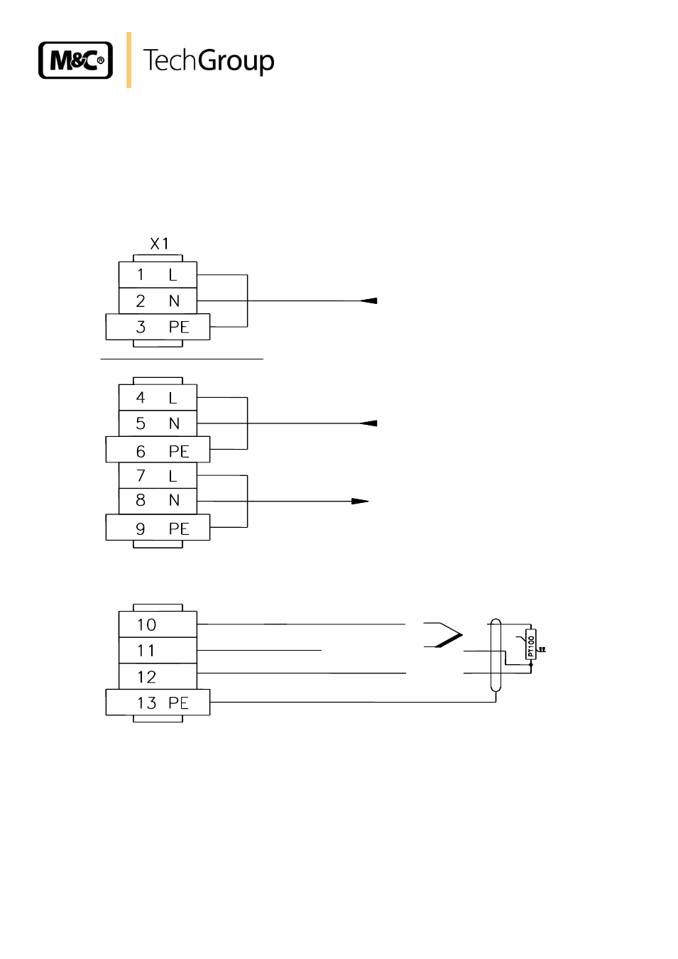
Figure 7 shows the possible connections of the electrical junction box X1 (B).
For devices from 12/2001 to 01/2008 with controller 703: thermocouple + at terminal 11, thermocouple
–
at terminal 12
Figure 7 Electrical junction box X1 (B)
The CSS is protected by fuse (F1= 2A, see wiring diagram in appendix). The fuse is located on the
main circuit board (see fig.4).
Elec
tri
ca
l j
un
ct
io
n b
ox
X1
Power In 230V 50Hz, 150VA for CSS
Option controller 70304 for heated sample line
Power In 150V 60Hz, 1100VA for heated sample line
Power In 150V 60Hz, 1100VA for heated sample line
Connection for the temperature sensor of the heated sample line
PT100 / thermocouple +
PT100 / thermocouple -
PT100 (3-wire)
screening
- SP10 Operator's manual (14 pages)
- N9 KP18 Operator's manual (21 pages)
- SP2000_20SS 150 Data sheet (3 pages)
- SP3100 Data sheet (6 pages)
- PSP4000-H _C _T Data sheet (4 pages)
- SP2200-H_C_I_BB_F Data sheet (2 pages)
- SP35-H... for gas sample probe SP2000-H... Data sheet (2 pages)
- FP-BF Data sheet (2 pages)
- SP3200 Operator's manual (28 pages)
- FPF-0,1 Operator's manual (2 pages)
- PSS-10_1 Operator's manual (23 pages)
- CSS-V2 Data sheet (3 pages)
- PMA 50 EEX Operator's manual (48 pages)
- MP30 Operator's manual (18 pages)
- SP2600-H_C_I_BB_F_0,1GF190 Data sheet (3 pages)
- SR25.1_Ex Operator's manual (22 pages)
- PMA 10S Operator's manual (27 pages)
- CSS-M_W Data sheet (3 pages)
- PAS-500 Operator's manual (20 pages)
- SP2000H320_DIL... Data sheet (3 pages)
- SP3200 Data sheet (6 pages)
- FA-1_2_3,bi Operator's manual (24 pages)
- SR25 Data sheet (2 pages)
- SP3000 Data sheet (4 pages)
- PAS Series Data sheet (2 pages)
- CG Series Data sheet (2 pages)
- ECP 20-2 Data sheet (3 pages)
- MP30-EX Data sheet (2 pages)
- PSP4000-H_C_T Operator's manual (24 pages)
- DIL-U Data sheet (2 pages)
- ADS-So Data sheet (2 pages)
- VC-2-SL Operator's manual (18 pages)
- ECM-ExII Operator's manual (39 pages)
- MP12 Operator's manual (17 pages)
- FPF+ Data sheet (2 pages)
- KS 2.Ex Operator's manual (17 pages)
- PMA 50 EEX Data sheet (3 pages)
- PMA 10S Data sheet (3 pages)
- Gas Sample Probes Series SP Data sheet (2 pages)
- BA-C Operator's manual (16 pages)
- MV3_2-H Series Operator's manual (18 pages)
- VC-2-SL Data sheet (3 pages)
- FM-200K-H_FA Operator's manual (16 pages)
- SP 30-H.._EX2 Operator's manual (16 pages)
- SP2006-H280_DIL Operator's manual (35 pages)