Function, Figure 6, Gas flow schematic – M&C TechGroup CSS Series Operator's manual User Manual
Page 16: 9function, Figure 6 gas flow schematic
16
Gas sampling and gas conditioning technology
4-1.1-ME
9
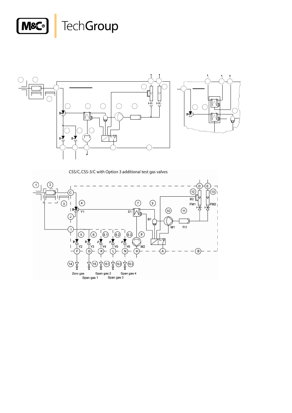
FUNCTION
The gas flow schematic of the CSS is shown in the following illustration.
13
12
11
10
9
7
4
5
8
6
3
2
1
F
G
H
D
E
C
FM1
FM2
A
B
B2
FI1
M1
B1
E1
Y1
Y2
Y3
M1
CSS; CSS-3
Zero
gas
Span
gas
9
7
4
C
B1
E1
Y1
M
K
L
CSS-2
3
L
F
K
13
12
11
10
Zero gas Span gas 1
9
7
4
5
8
6
14
15
2
1
G
H
D
E
C
FM1
FM2
A
B
B2
Fl1
M1
B1
E1
Y1
Y2
Y3
M2
I
Span gas 2
15.1
Y4
6.1
Span gas 3
Y5
6.2
Span gas 4
Y6
6.3
N
15.2
15.3
J
CSS/C; CSS-3/C with option 03G9030 (a)
Figure 6 Gas flow schematic
Principally, there are two main ways for gas to enter and flow through the CSS:
- sample gas flow (C, 4, 7, 9, 10, 12 and 13, D and E);
(version CSS-2 additional: M, 7, K);
- test gas flow (F or G, 5 or 6, 4, 7, 9, 10, 11, 12 and 13, D or E)
(Version CSS.../C: F or G, 5 or 6, I, 2, C, 4, ... see above).
The gas sample pump (10) transports the sample gas via the gas sample probe, consisting of a sam-
ple tube (1) and a filter (2), to the CSS. The heated sample line (3) is connected at the sample gas
inlet (C). In order to prevent early condensation of the sample gas, components (2) and (3) are
heated.
In the measuring mode, the 3-way solenoid valve (4) allows the flow to the gas cooler (7).
The dew point of the gas is maintained at a stable value of +5°C +/- 0,1 °C (for further specifications
see appendix).