Figure 5, Back-panel of the 19" rack housing, A1 l k h n – M&C TechGroup CSS Series Operator's manual User Manual
Page 15
15
Gas sampling and gas conditioning technology
4-1.1-ME
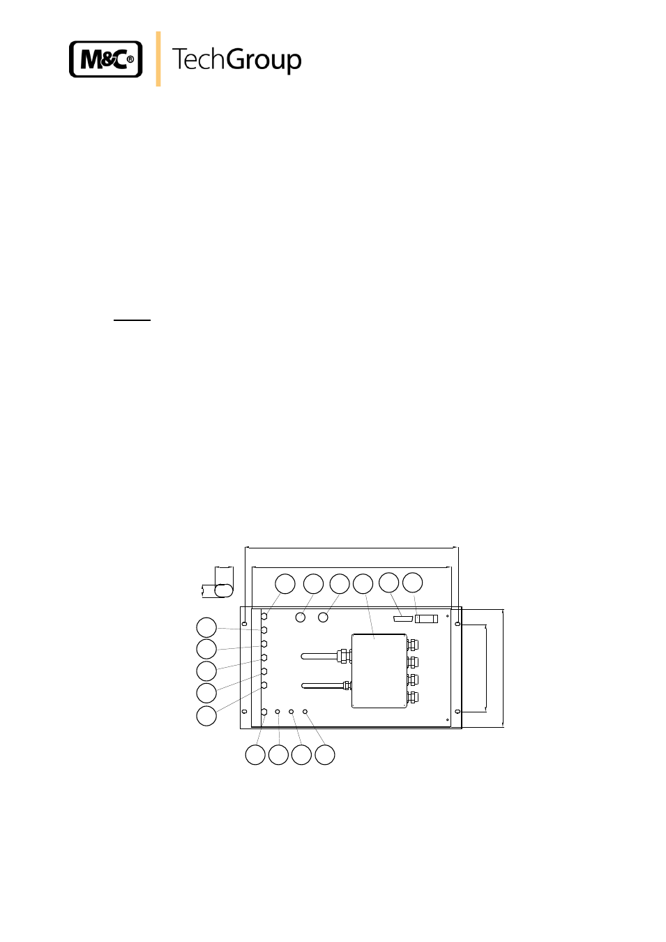
All the electrical and tube-/hose connections are located on the back panel of the 19" rack housing.
These are:
(A) Sub-D-Plug X2 (see 10.2):
device status
- external status inquiry
measuring/test mode
internal ( the link between pin 1 and 9 is factory installed and
- control functions
must exist for the local control to function)
external (with potential free contacts)
(A1) Reserve
(B) electrical junction box X1 (see 10.1):
- power supply
- option: connection heated sample line and temperature-sensor
(C)* sample gas inlet
(D) sample and test gas outlet 1 with Flow-Alarm
(E) sample and test gas outlet 2
(F) zero gas inlet
(G) span gas inlet
(H) condensate outlet
(I) test gas to the probe**
(J) ventilation**
(K) option: span gas 2 inlet, condensate outlet 2***
(L) option: span gas 3 inlet, sample gas outlet 3***
(M) sample gas inlet 2***
(N) option: span gas 4 inlet
10
7
435
258
X 1
Status X2
465
190,5
A
C
G
B
F
D
E
I
J
M
Power
connection
A1
L
K
H
N
Figure 5 Back-panel of the 19" rack housing
* (C) - (M) a
re PVDF G 1/4“ i fittings
** only version CSS.../C, test gas to probe
*** only version CSS-2