Liquid- and flow alarm card lfc-2, 3 liquid- and flow alarm card lfc-2 – M&C TechGroup CSS Series Operator's manual User Manual
Page 22
22
Gas sampling and gas conditioning technology
4-1.1-ME
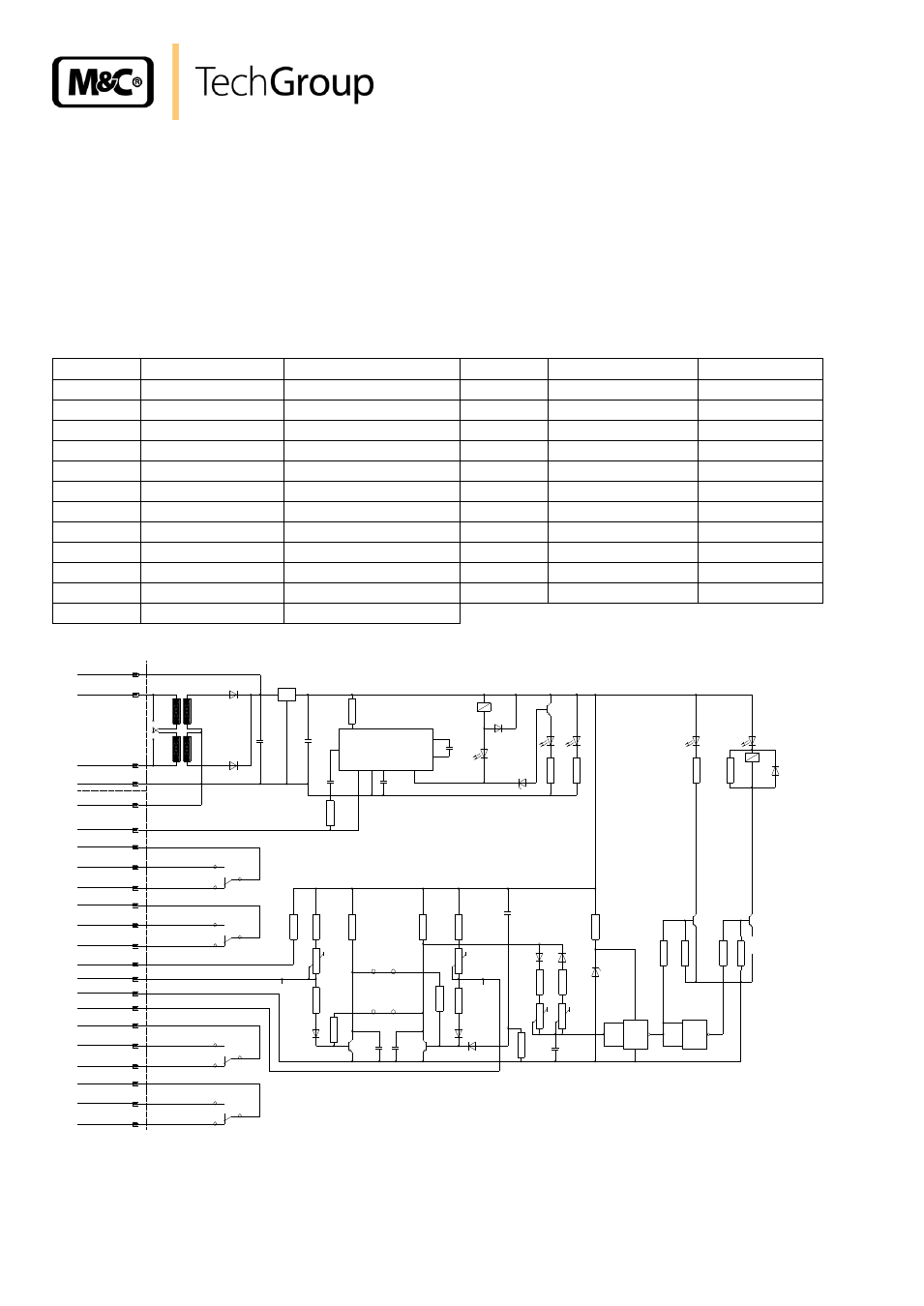
10.3 LIQUID- AND FLOW ALARM CARD LFC-2
The LFC-2 is a combined electronic card operating the flow alarm sensor FA1bi and the liquid alarm
sensor LA1.
Pulsating gas flow can release a unintentional flow alarm. To avoid this the LFC-2 is equipped with
slow operation -time lag to eliminate the alarm- and slow release -alarm with time lag. Times in be-
tween 3 and 13 seconds (3 seconds are factory-aligned) are continuously adjustable by the potenti-
ometers P5 and P6 (see Fig. 11, wiring diagram LFC-2). For more specific information about the liquid
alarm sensor LA1 and the flow alarm sensor FA1bi please see the data sheets 5-6.10.1 and 5-5.1.1.
The plan of terminal connections is displayed in the following chart.
Terminal
Path
Connections
Terminal
Path
Connections
d2
power 230/115V L
d32
alarm contact 2
NC
z2
power 230/115V N
d12
FA sensor
brown
z4
power 230/115V PE
d16
FA sensor
green
d4
supply
+15V up to +24V DC d14
FA sensor
white
z4
supply
0V DC
z16
FA sensor
yellow
d8
LA sensor
shielding
z22
alarm contact 1
MC
z8
LA sensor
white
d22
alarm contact 1
NO
z28
alarm contact 1
MC
z24
alarm contact 1
NC
d28
alarm contact 1
NO
d24
alarm contact 2
MC
z30
alarm contact 1
NC
z26
alarm contact 2
NO
d30
alarm contact 2
MC
d26
alarm contact 2
NC
z32
alarm contact 2
NO
+
+
+
LM1830
IC2
5
10
11
+
9
47nF
12
1
7
14
+
3,9nF
gn
rt
gn
rt
gn
K1
K1
100nF
100nF
B5-bi
mono=offen
bi=geschlossen
B4+B5
B4-bi
open at mono
120-200mV
120-200mV
1µF
+
+
22µF
&
14
1
2
7
3
4
&
6
5
IC3 4093
br=brown/braun
gn=green/grün
rt=red/rot
ws=white/weiß
ge=yellow/gelb
V2-V5 Transistoren BC 239C
D3;D8-D12;D14 Dioden 1N4148
Relais K1;K2 max. 250V DC/AC 90W,250VA,1A
LFC-2 01E1385 T1=3,5VA Frontplatte 6TE
LFC-2CSS 03E2026 T1=7VA ohne Frontplatte
P5 = switch-off-hysterysis 3-13 sec.
P5 = Alarmfreigabeverzögerung 3-13 sek.
P6 = Alarmfreigabeverzögerung 3-13 sek.
P6 = switch-off-hysterysis 3-13 sec.
10-100k
K2
K2
X1
(DC +15V-24V)
d2
B2 115V
B1 230V
B3 115V
d4
z2
L 230V/115V
N 230V/115V
z4
(PE/DC 0V)
LA-Sensor
d8
LA-Sensor ws
z8
LA 1MC
z28
LA 1NO
d28
LA 1NC
z30
LA 2NC
LA 2NO
LA 2MC
d32
z32
d30
d12
FA-Sensor gn
d16
FA-Sensor ge
z16
FA-Sensor ws
d14
FA 2MC
FA 2NO
FA 2NC
d24
z26
d26
FA 1NC
FA 1MC
FA 1NO
z24
z22
d22
Steckerleiste DIN 41612 F-d/z
2x115V/2x15 3,5VA
T1
4
1N4007
D1
4
1N4007
D2
4
230V
B1 geschlossen/close
B2;B3 offen/open
115V
V
B2;B3 geschlossen/close
B1 offen/open
FA-Sensor br
470µF
C1
35V
IC1
7812
1µF
C2
35V
C3
35V
47µF
C4
35V
C5
35V
D5
R2
470
D3
K1
D6
D7
ZPD 5,6
D4
1k
R3
3k3
R24
BC239C
V1
D16
D15
3k3
R21
1k
R22
K2
D14
R1
39k
V4
V5
R17
47k
R18
220k
R19
47k
R20
220k
C8
35V
C9
16V
D13
ZPD9.1
R23
470k
R16
100k
R15
100k
P6
1M
P5
1M
R14
10k
R12
15k
R10
10k
P2
200k
R13
1k5
R11
56k
D9
D10
D11
D12
R8
10k
R6
15k
C7
35V
C6
35V
V3
V2
R9
56k
R7
56k
D8
P1
200k
R5
330