M&C TechGroup CSS Series Operator's manual User Manual
Page 12
12
Gas sampling and gas conditioning technology
4-1.1-ME
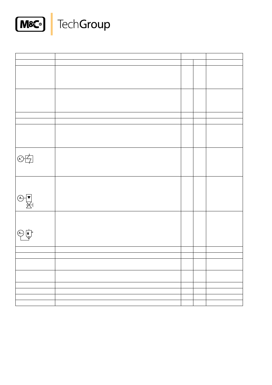
The following chart describes the functions of the operation and control board.
Function
Description
Switch
LED
l
r
Local Control
(intern)
control of the CSS with operation and control board;
link between pin 1 and 9 (connector X2, s. 10.2.2);
control power supply;
(dual col-
oured)
green
External Control
(extern)
external control with Sub-D-Plug X2 (s. 10.2.3),
switches of the operation and control board out of
function; control power supply after switching the CSS
on ;
(dual col-
oured)
red
On
internal control activated;
X
green*
Off
switches CSS off
X
no LED
Status
no alarm: CSS ready for operation;
alarm : cooler-/temperature-controller alarm;
flow alarm;
liquid alarm.
green*
red*
Cooler- Alarm
no alarm: CSS ready for operation;
alarm : CSS not ready for operation,
temperature of cooler <2°C or >8°C,
or optional temperature-controller:
controller not in range
green*
red*
Flow-
Alarm
no alarm: CSS in operation;
alarm : no gas flow (i.e. inlet or outlet
is blocked),
sample gas pump not in operation,
liquid alarm,
cooler-/temperature-controller alarm;
green*
red*
Liquid-
Alarm
no alarm: CSS ready for operation
alarm : condensate alarm;
green*
red*
Pump Off
sample gas pump off;
X
red
Pump On
sample gas pump on;
X
green*
Measure
CSS in sample mode,
signal contact available;
X
yellow*
Check
CSS in test mode,
signal contact available;
X
yellow*
Sample Gas
3-way solenoid valve open for sample mode;
X
yellow*
Test Gas
3-way solenoid valve open for test mode;
X
yellow*
Zero Gas
2-way solenoid valve open for Zero Gas;
X
yellow*
Span Gas
2-way solenoid valve open for Span Gas;
X
yellow*
* LED display also for external control