Figure 2, Operation and control board – M&C TechGroup CSS Series Operator's manual User Manual
Page 11
11
Gas sampling and gas conditioning technology
4-1.1-ME
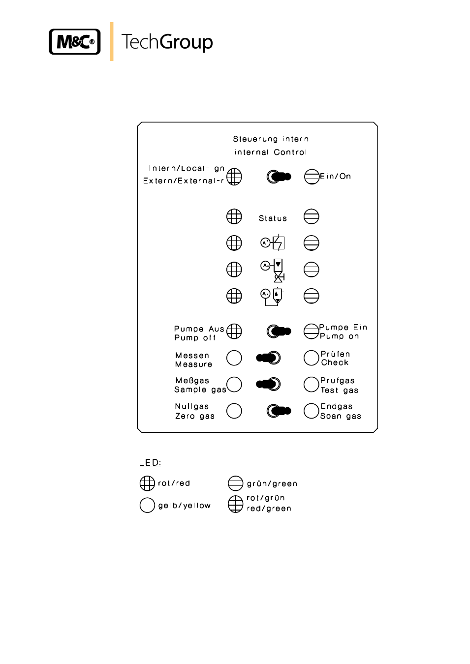
Figure 2 shows the operation and control board (1.1). The different functions are selected by toggle
switches and indicated with LED’s. The internal or external function is configured through the wiring in
the Sub-D-Plug (see 4.1) and indicated by a dual coloured LED on the operation and control board.
Figure 2 Operation and control board
See also other documents in the category M&C TechGroup Equipment:
- SP10 Operator's manual (14 pages)
- N9 KP18 Operator's manual (21 pages)
- SP2000_20SS 150 Data sheet (3 pages)
- SP3100 Data sheet (6 pages)
- PSP4000-H _C _T Data sheet (4 pages)
- SP2200-H_C_I_BB_F Data sheet (2 pages)
- SP35-H... for gas sample probe SP2000-H... Data sheet (2 pages)
- FP-BF Data sheet (2 pages)
- SP3200 Operator's manual (28 pages)
- FPF-0,1 Operator's manual (2 pages)
- PSS-10_1 Operator's manual (23 pages)
- CSS-V2 Data sheet (3 pages)
- PMA 50 EEX Operator's manual (48 pages)
- MP30 Operator's manual (18 pages)
- SP2600-H_C_I_BB_F_0,1GF190 Data sheet (3 pages)
- SR25.1_Ex Operator's manual (22 pages)
- PMA 10S Operator's manual (27 pages)
- CSS-M_W Data sheet (3 pages)
- PAS-500 Operator's manual (20 pages)
- SP2000H320_DIL... Data sheet (3 pages)
- SP3200 Data sheet (6 pages)
- FA-1_2_3,bi Operator's manual (24 pages)
- SR25 Data sheet (2 pages)
- SP3000 Data sheet (4 pages)
- PAS Series Data sheet (2 pages)
- CG Series Data sheet (2 pages)
- ECP 20-2 Data sheet (3 pages)
- MP30-EX Data sheet (2 pages)
- PSP4000-H_C_T Operator's manual (24 pages)
- DIL-U Data sheet (2 pages)
- ADS-So Data sheet (2 pages)
- VC-2-SL Operator's manual (18 pages)
- ECM-ExII Operator's manual (39 pages)
- MP12 Operator's manual (17 pages)
- FPF+ Data sheet (2 pages)
- KS 2.Ex Operator's manual (17 pages)
- PMA 50 EEX Data sheet (3 pages)
- PMA 10S Data sheet (3 pages)
- Gas Sample Probes Series SP Data sheet (2 pages)
- BA-C Operator's manual (16 pages)
- MV3_2-H Series Operator's manual (18 pages)
- VC-2-SL Data sheet (3 pages)
- FM-200K-H_FA Operator's manual (16 pages)
- SP 30-H.._EX2 Operator's manual (16 pages)
- SP2006-H280_DIL Operator's manual (35 pages)