English – ASRock Fatal1ty Z77 Professional User Manual
Page 38
38
Fatal1ty Z77 Professional Series Motherboard
English
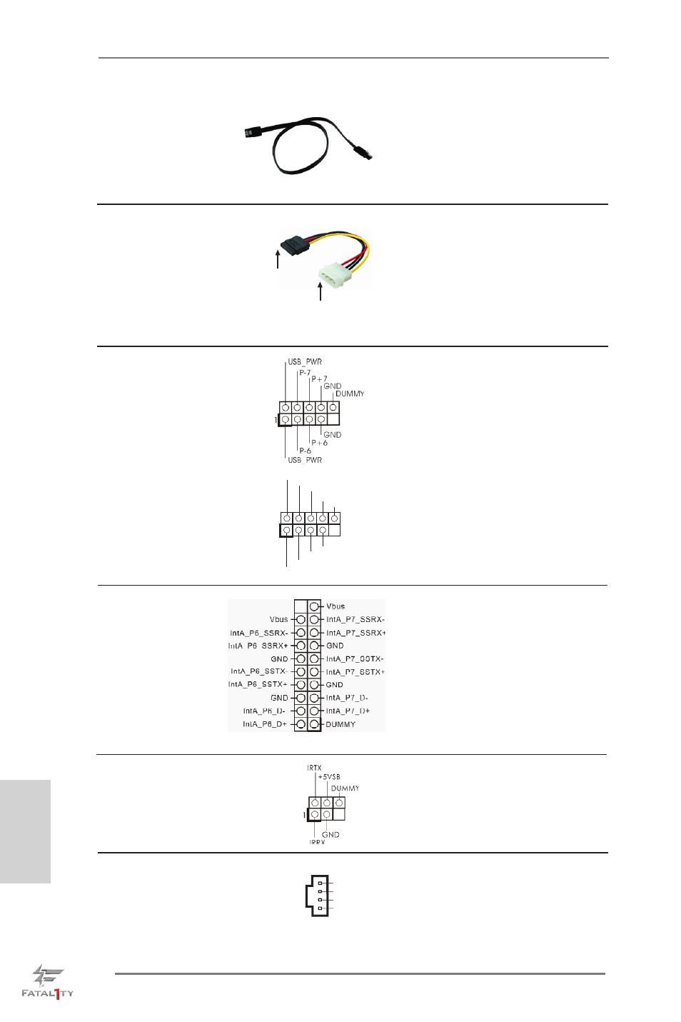
Serial ATA (SATA)
Either end of the SATA data
Data Cable
cable can be connected to the
(Optional)
SATA / SATA2 / SATA3 hard
disk or the SATA2 / SATA3
connector on this motherboard.
USB 2.0 Headers
Besides six default USB 2.0
(9-pin USB_6_7)
ports on the I/O panel, there are
(see p.4, No. 24)
two USB 2.0 headers on this
motherboard. Each USB 2.0
header can support two USB 2.0
ports.
(9-pin USB_8_9)
(see p.4, No. 25)
Serial ATA (SATA)
Please connect the black end
Power Cable
of SATA power cable to the
(Optional)
power connector on each drive.
Then connect the white end of
SATA power cable to the power
connector of the power supply.
connect to the
power supply
1
USB_PWR
P-8
GND
DUMMY
USB_PWR
P+8
GND
P-9
P+9
Infrared Module Header
This header supports an
(5-pin IR1)
optional wireless transmitting
(see p.4, No. 29)
and receiving infrared module.
USB 3.0 Header
Besides six default USB 3.0
(19-pin USB3_6_7)
ports on the I/O panel, there is
(see p.4, No. 9)
one USB 3.0 header on this
motherboard. This USB 3.0
header can support two USB 3.0
ports.
Internal Audio Connectors
This connector allows you
(4-pin CD1)
to receive stereo audio input
(CD1: see p.4 No. 42)
from sound sources such as
a CD-ROM, DVD-ROM, TV
tuner card, or MPEG card.
CD1
CD -L
GND
GND
CD -R
connect to the SATA
HDD power connector