6 general mvr configuration, Figure 69 mvr multicast television example – ZyXEL Communications GS-2724 User Manual
Page 159
Chapter 22 Multicast
GS-2724 User’s Guide
159
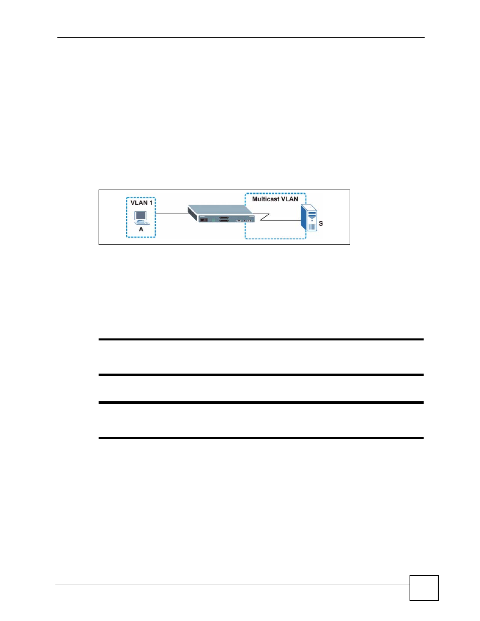
When the subscriber selects a television channel, computer A sends an IGMP report to the
Switch to join the appropriate multicast group. If the IGMP report matches one of the
configured MVR multicast group addresses on the Switch, an entry is created in the
forwarding table on the Switch. This maps the subscriber VLAN to the list of forwarding
destinations for the specified multicast traffic.
When the subscriber changes the channel or turns off the computer, an IGMP leave message is
sent to the Switch to leave the multicast group. The Switch sends a query to VLAN 1 on the
receiver port (in this case, a DSL port on the Switch). If there is another subscriber device
connected to this port in the same subscriber VLAN, the receiving port will still be on the list
of forwarding destination for the multicast traffic. Otherwise, the Switch removes the receiver
port from the forwarding table.
Figure 69 MVR Multicast Television Example
22.6 General MVR Configuration
Use the MVR screen to create multicast VLANs and select the receiver port(s) and a source
port for each multicast VLAN. Click Advanced Applications > Multicast > Multicast
Setting > MVR to display the screen as shown next.
"
You can create up to three multicast VLANs and up to 256 multicast rules on
the Switch.
"
Your Switch automatically creates a static VLAN (with the same VID) when you
create a multicast VLAN in this screen.