Hardware connections, Safety warnings, Front panel – ZyXEL Communications ZyXEL Dimension ES-3124 User Manual
Page 37: Chapter 3 hardware connections, 1 safety warnings, 2 front panel
Dimension ES-3124 Ethernet Switch
Hardware Connections
3-1
Chapter 3
Hardware Connections
This chapter acquaints you with the front and rear panels, shows you how to make the connections,
install/remove (optional) modules and explains the LEDs.
3.1 Safety Warnings
¾
The length of exposed (bare) power wire should not exceed 7mm.
¾
Do not use this product near water, for example, in a wet basement.
¾
Only a qualified technician should service or disassemble this device.
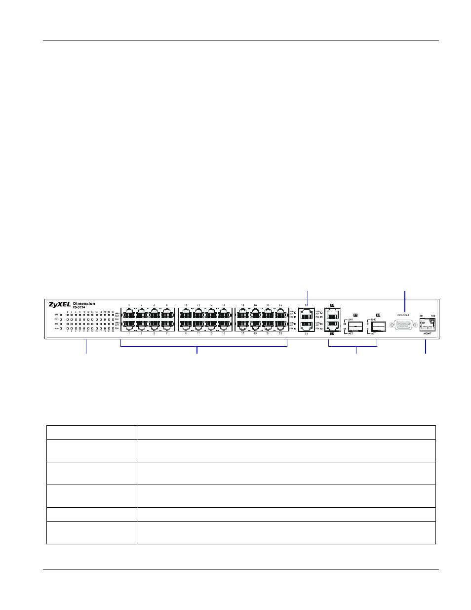
3.2 Front Panel
The following figure shows the front panel of the ES-3124. The front panel contains switch LEDs, 24 RJ-45
Ethernet ports, four RJ-45 Gigabit ports, 2 mini GBIC ports, and a console port and a management port for local
switch management.
Figure 3-1 ES-3124 Front Panel
The following table describes the ports on the front panel.
Table 3-1 ES-3124: Front Panel Ports
CONNECTOR DESCRIPTION
24 10/100 Mbps RJ-45
Ethernet connectors
Connect these ports to a computer, a hub, an Ethernet switch or router.
Four 100/1000 Mbps
RJ-45 Gigabit Ports
Connect these 1Gbps Ethernet ports to high-bandwidth backbone network Ethernet
switches or use them to daisy-chain other switches.
Two Mini GBIC Ports
Use mini GBIC transceivers in these slots for fiber-optical connections to backbone
Ethernet switches.
Console Port
The console port is for local configuration of the switch.
Management Port
Connect to a computer using an RJ-45 Ethernet cable for local configuration of the
switch.
Ethernet Ports
RJ-45 Gigabit / Mini GBIC
Combo Ports for uplink
LEDs
Management Port
Console Port
RJ-45 Gigabit Ports for stacking