Zhone Technologies 900 User Manual
Page 80
2-14
IMACS System Release 5.1.6
Data Cards
Model No.
Running Head
Card Configuration Examples
SRU Card
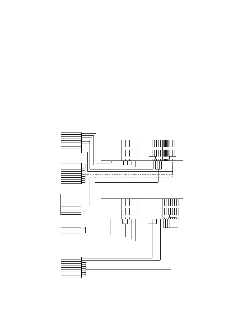
WAN 1-1, TS 4 has b-20 framing and will support up to twenty 0.3, 1.2 or 2.4 kbps circuits
from two (or more) SRU cards. In this example, SRU 1, port 10 is assigned to SRU TS 1, SRU
2, ports 1-10 are assigned to SRU TS 2 to11. The nine SRU time slots left are used by SRU 3,
ports 1-9. As mentioned earlier, SRU 3, port 10 is a 9.6 kbps circuit assigned to WAN 1-1, TS
2, SRU time slot 5. WAN 1-1, TS 5, has a framing. Only one device can transmit data in this
SRU time slot. In this example, a 2.4 kbps circuit was assigned to SRU 4, port 5.
WAN 1-1, TS 6 has b-5 framing, so five SRU time slots are available. The first two 9.6 kbps
slots are used by a 19.2 kbps circuit on SRU 4, port 6, while the other three are used by 9.6
kbps circuits on SRU 4, ports 7 to 9.
WAN 1-1, TS 7 has the same characteristics as TS 6, except that the first SRU time slot is used
by a 9.6 kbps circuit on SRU 4, port 10, SRU time slots 2-4 are assigned to the single 28.8
kbps port on SRU 5. WAN 1-1, TS 8 was designated as b-10 framing and the first eight SRU
time slots are associated with the 2.4 and 4.8 kbps circuits on SRU 5, ports 3 to10.
Figure 2-9. Typical WAN Time Slot Assignments to an SRU Card
TS #1
TS #2
TS #3
TS #4
WAN CARD #1 PORT #1
SRU TS
1
1
2
3
4
5
TS #5
TS #6
TS #7
TS #8
WAN CARD #1 PORT #1
1
1
2
3
4
5
1
2
3
4
5
SRU #1
SRU TS
28.8
38.4
9.6
4.8
4.8
4.8
4.8
4.8
4.8
2.4
SRU #2
2.4
2.4
2.4
2.4
2.4
2.4
2.4
2.4
2.4
2.4
SRU #3
2.4
2.4
2.4
2.4
2.4
2.4
2.4
2.4
2.4
9.6
SRU #4
4.8
4.8
2.4
2.4
2.4
19.2
9.6
9.6
9.6
9.6
SRU #5
9.6
28.8
4.8
4.8
2.4
4.8
4.8
2.4
4.8
4.8
1-10
1-20
1-10
Port #
1
2
3
4
5
6
7
8
9
10
Port #
1
2
3
4
5
6
7
8
9
10
Port #
1
2
3
4
5
6
7
8
9
10
Port #
1
2
3
4
5
6
7
8
9
10
Port #
1
2
3
4
5
6
7
8
9
10