Figure 6-5. local network loopback lb gen mode, Lb gen – Zhone Technologies 900 User Manual
Page 168
6-8
IMACS System Release 5.1.6
Data Cards
Model No.
Running Head
PM-IOR Card User Screens and Settings
PM-IOR Card
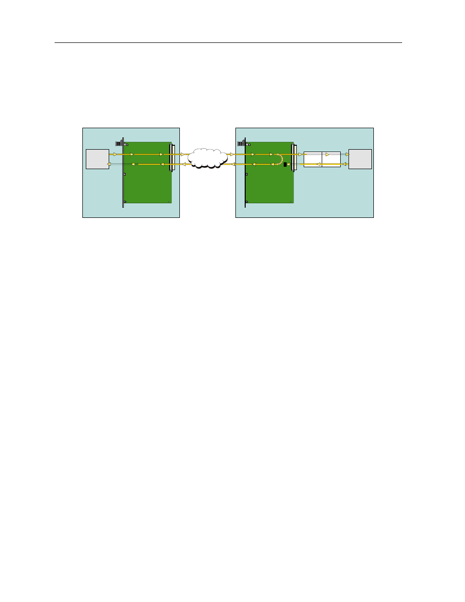
Choose the net (network) setting to loop the incoming data from the network back toward the
far end. This loopback is shown in Figure 6-5. It tests some of the local PM-IOR Card
circuitry, the local system common cards, the WAN link card, the far-end PM-IOR Card and
CPE device, and the WAN link between the two sites.
Figure 6-5. Local Network Loopback
LB GEN MODE
The Loopback Generation Mode (LB GEN MODE) setting defines the type of inband loop-up
and loop-down codes that will be sent to the remote equipment. Three industry-standard codes
are supported: dds, which sends a DDS-compatible latching loopback code in each of the
DS0s that make up the circuit; v.54, which is compatible with CCITT V.54 standard and ft1,
which is compatible with ANSI Fractional T1 standards.
On the PM-IOR Card, the same choices above appear if the port mode is set to dce. For a dte
port, this setting is always n/a.
LB GEN
If you selected v.54 or ft1 as the Loopback Generation (LB GEN) mode setting, the Loopback
Generation setting allows you to send an on (loop-up command) or off (loop-down
command). If you selected dds as the Loopback Generation mode, this setting allows you to
define the type of DDS loopback that you wish to generate. The four options are ocu (Office
Channel Unit), dsu (Data Service Unit), csu (Channel Service Unit), and ds0 (a full 64 kbps
loopback). Figure 6-6 through Figure 6-8 show where these loopbacks occur. You can also
turn all DDS remote loopbacks off.
Note that you cannot perform loop-up and loop-down commands on more than one port of the
same card simultaneously. You must finish all loopback operations on one port before starting
them on another port.
OCU-DP Card
PM-IOR Card
CSU
DSU
Local
DTE
Remote
DTE
Carrier's DDS
Network
Local System
Local Site
Remote Site
Remote System