4 card configuration examples, Sru card card configuration examples – Zhone Technologies 900 User Manual
Page 79
Data Cards
IMACS System Release 5.1.6
2-13
SRU Card
Card Configuration Examples
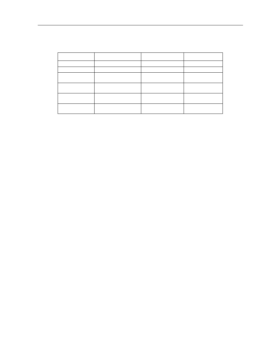
Table 2-4. Bit Error Rates for Majority-Vote Error Correction
2.4
Card Configuration Examples
Figure 2-9 shows ways in which SRU cards can be used to network low-speed data with DS0A
and DS0B framing. In this diagram, five cards are connected to eight WAN time slots of one
WAN port on one WAN card (many combinations of cards/ports/time slots are possible). Each
card is separated to show the ten ports on each card. Each port is assigned to a low-speed data
device, and the transmission speed of that device is shown in the center of the SRU data port.
Note that the diagram sometimes shows only one connection, in order to eliminate
unnecessary lines in the diagram. Each port is a direct connection and does not support
interchange of data transmission between ports.
The first time a WAN card/port/time slot is used, the framing selected on the SRU card port
will segregate that WAN time slot into SRU time slots. Once selected, those SRU TSs will
apply to all ports assigned to that WAN time slot.
Once the framing is selected for the WAN card/port/time slot, low-speed data devices can be
arranged and selected on the SRU card settings to maximize the system capabilities.
In this example, the first port on SRU 1 assigned a framing to WAN 1-1, TS 1, and selected a
38.4 kbps device for its use. The second port has b-5 framing to WAN 1-1, TS 2. Of the five
SRU time slots on that WAN time slot, the first three are used to support a 28.8 kbps device
(three 9.6 kbps contiguous SRU time slots). The 9.6 kbps device on SRU 1, port 3 occupies
the fourth SRU time slot and another 9.6 kbps from SRU 3, port 10 is placed in the fifth slot.
WAN 1-1, TS 3 was segregated into ten SRU time slots by the selection of b-10 framing,
which supports 0.3, 1.2, 2.4, or 4.8 kbps transmission. Six 4.8 kbps ports are assigned to the
first six SRU time slots. The diagram shows only one connection to eliminate unnecessary
lines in the diagram. The six ports are six direct connections and will not support interchange
of data transmission. The other four SRU time slots are used by ports 1 to 4 on SRU 4. Again,
the single line does not imply interexchange.
Threshold
EER Set
EER Reset
Period
none
none
none
none
10e-3
64 or more errors
63 or less errors
1 second
10e-4
64 or more errors
or any of the above
63 or less errors
10 seconds
10e-5
38 or more errors
or any of the above
37 or less errors
60 seconds
10e-6
3 or more errors
or any of the above
2 or less errors
60 seconds
10e-7
17 or more errors
or any of the above
16 or less errors
three 15 minute time
intervals