Rear panel – RGB Spectrum Quadra User's Guide User Manual
Page 19
I N S T A L L A T I O N A N D S E T U P
Rear Panel
350-7951
Quadra User’s Guide
11
.
. .
.
.
. . . . . . . . . . . . . . . . . . . . . . . . . . . . .
R E A R P A N E L
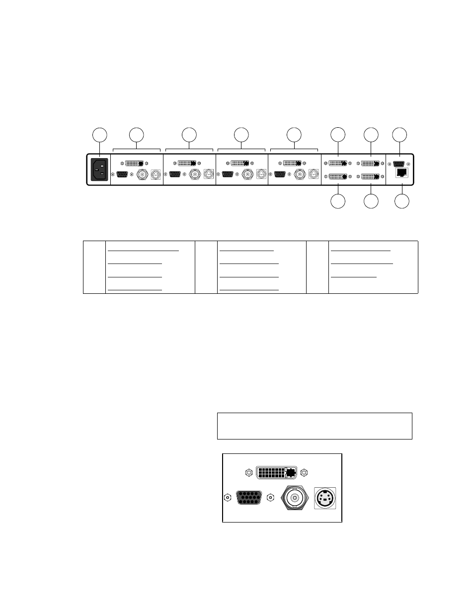
The figure below shows a view of the Quadra rear panel.
Figure 2-2.
Quadra
Rear Panel View
Descriptions of each section and connector are provided below:
1)
AC Power Connector
One
AC Power Connector
(IEC 320 three pin) is provided for the
system’s universal power supply, which operates from any power
source with a line voltage in the range of 100 - 260 VAC.
2)
Input Channel 1
Up to four connectors are provided for
Input Channel 1
, as
illustrated and described below. This input supports composite,
RGB/component, S-Video and (optionally) DVI signals.
Figure 2-3.
Input Channel Connectors
RS-232
10/100 BaseT
Output - 1
Holes
Holes
Holes
DVI-2
DVI-3
DVI-4
Composite-2
RGB-2
S-Video-2
Composite-3
RGB-3
S-Video-3
Composite-4
RGB-4
S-Video-4
Holes
Composite-1
RGB-1
S-Video-1
DVI-1
Output - 2
Output - 3
Output - 4
6
2
3
4
5
7
8
9
10
11
1
1)
5)
Input Channel 4
9)
2)
6)
Graphic Output 1
10)
3)
7)
Graphic Output 2
11)
4)
Input Channel 3
8)
Note
Click on a connector below to learn more about the
connector’s specifications.