Dvi-i connector, Connector type and pinouts, Dvi-1 – RGB Spectrum Quadra User's Guide User Manual
Page 110
C O N N E C T O R TY P E S
DVI-I Connector
350-7951
Quadra User’s Guide
102
.
. .
.
.
. . . . . . . . . . . . . . . . . . . . . . . . . . . . .
D V I- I C O N N E C T O R
The DVI connector is used to interconnect graphics devices. This is a standard
connector based on the work of the Digital Display Working Group (DDWG).
CONNECTOR TYPE
. . . . . . . . .
AND PINOUTS
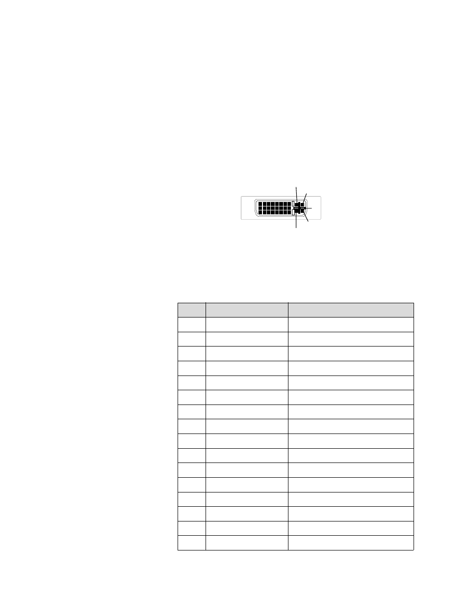
The connector used in Quadra is a 29-pin DVI-I connector, supporting both
analog and digital signals. The DVI-I connector (as shown below) is used for
Quadra’s four standard DVI output channels and for each channel’s optional
digital DVI input.
Figure C-4.
DVI-I Digital/Analog Connector (viewed from rear of chassis
The 29-pin DVI-I connector has the following signals:
Table C-4.
DVI-I Connector Pinouts
Pin
Signal
Description
1
TMDS Data 2-
2
TMDS Data 2+
3
TMDS Data 2/4 shield
4
NC
Defined for Dual Link only
5
NC
Defined for Dual Link only
6
DDC Clock
7
DDC Data
8
Analog Vertical Sync
Horizontal sync is on pin C4
9
TMDS Data 1-
10
TMDS Data 1+
11
TMDS Data 1/3 shield
12
NC
Defined for Dual Link only
13
NC
Defined for Dual Link only
14
+5V Power
5 V fused @ 300mA.
15
Ground
16
Hot Plug detect
1
17
9
8
24
C1
C2
C3
C4
C5