Rs-232 connector, Connector type and pinouts, Null modem – RGB Spectrum Quadra User's Guide User Manual
Page 113: Connector type and pinouts null modem
C O N N E C T O R TY P E S
RS-232 Connector
350-7951
Quadra User’s Guide
105
.
. .
.
.
. . . . . . . . . . . . . . . . . . . . . . . . . . . . .
R S - 2 3 2 C ON N E C T OR
The RS-232 port is configured according to the Electronic Industries
Association Standard RS-232-C published in August 1969. The Quadra can be
explicitly controlled with ASCII Command Set instructions sent via the RS-232
serial port from either a computer or an ASCII terminal. In Chapter 4, refer to
the “
” section for details on all commands.
CONNECTOR TYPE
. . . . . . . . .
AND PINOUTS
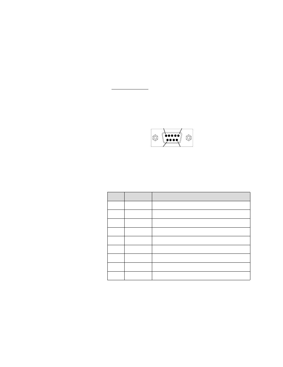
Physically, the RS-232 port is a 9-pin D-Sub female connector. The pins for the
RS-232 connector are numbered from top to bottom, right to left. Looking at
the connector, pin #1 is located in the upper right corner, and pin #9 is in the
lower left corner.
Figure C-6.
9-pin D-Sub RS-232 Female Connector
The 9-pin D-Sub connector has the following signals:
. . . . . . . . .
NULL MODEM
You may need to connect Quadra’s serial port to a computer configured as Data
Communications Equipment (DCE). This is accomplished using a null modem.
The net effect of a null modem is to reverse the Transmitted Data and
Received Data connections within the cable. Also, the Request to Send (RTS)
and Clear to Send (CTS) connections are reversed. This may be done by using
a special “null modem” cable, or by inserting a small “null modem” box or
cable in series with a regular “straight through” cable.
Table C-6.
RS-232 Serial Connector Pinouts
Pin
Circuit
Description
1
CD
Carrier Detect
2
TD
Transmit Data
3
RD
Received Data
4
(not connected)
5
AB
Signal Ground (common return)
6
DSR
Data Set Ready
7
CTS
Clear to Send
8
RTS
Request to Send
9
(not connected)
Holes
1
5
9
6