Pioneer RM V2550BU User Manual
Page 97
87
ADJUSTMENTS
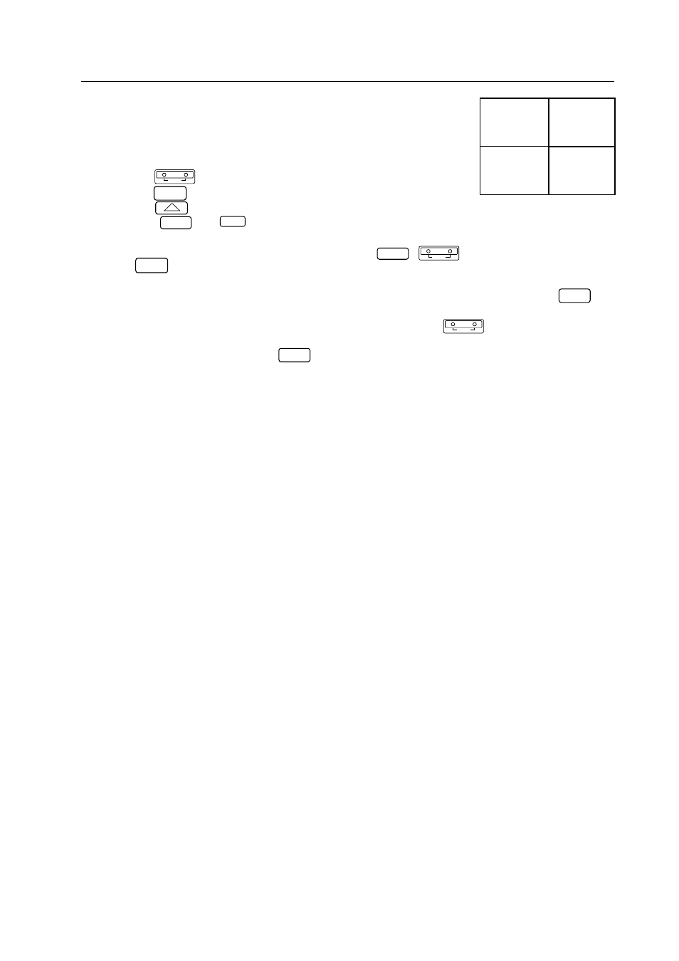
ID = 04
ID = 02
ID = 01
123456789012345678
123456789012345678
123456789012345678
123456789012345678
123456789012345678
123456789012345678
123456789012345678
123456789012345678
123456789012345678
123456789012345678
123456789012345678
123456789012345678
123456789012345678
123456789012345678
ID = 03
Use this function to select the screen to be adjusted from the remote control
unit.
Example: To select the screen at the lower left in the diagram at the right (ID
= 03):
[1] Use the
ADJ IN
key to set all the screens to the adjustment mode.
[2] Use the
1
key to select “1. ID SET/CLEAR/SELECT”.
[3] Use the
2
key to select “2. ID SELECT”.
[4] Press the
0
and
3
keys (ID = 03).
[5] The main menu display appears on the screen at the lower left only, and
the other screens are in the standby mode (only the
POWER
,
ADJ IN
and
ADJ OUT
keys will work).
¶ To return to the main menu screen after selecting the screen using the ID number, operate the
MAIN MENU
key.
The ID select mode is held.
It is also possible to return to the main menu screen by operating the
ADJ IN
key. In this case, however,
the ID select mode is canceled, so start over from step [1].
To select another screen, use the
MAIN MENU
key to return to the main menu screen, then change the ID
number in step (4) above.
NOTE) If you specify the wrong ID number
Repeat steps [1] to [5] above. In addition, a non-existent ID number can be input (for
example, “33” in the above case), but in this case all the screens are set to the standby
mode.
If a unit’s ID number has been cleared, it is no longer possible to communicate with the units connected by
ABL linking cables after that unit. When the “**IDC” command is issued at the diagram on the previous page,
only the first unit can be controlled. Control of the second unit is enabled by issuing the “01IDS” command.
Control of units connected subsequently is enabled by assigning ID numbers in the same way.