Rear panel, 1 vbs/ y/c switch, 3 input switch – Pioneer RM V2550BU User Manual
Page 26: 4 remote control input connector, 5 rs-232c switch, 6 rs-232c connector, 16 general specifications, Input output
16
GENERAL SPECIFICATIONS
INPUT
OPTION
V.FIL
ON OFF
(Y/C)
Y/C
Y
C
G
B
R
H/CS
V
(Y)
(C)
INPUT
OUTPUT
FUSE 125V 3.15A
AC INLET
V IN
V OUT1
V OUT2
V OUT3
V OUT4
CONTROL
IN
OPTION
V IN
DISPLAY
MVP
RATE
RS-232C
MODE
COMB
OUT
VBS
VBS
G
B
R
VBS
Y
C
G
B
R
VBS
Y
C
G
B
R
VBS
Y
C
G
B
R
VBS
Y
C
VBS
( )
VBS
( )
2
1
3 4
6
7
8 9 0 - =
%
$
#
@
!
~
5
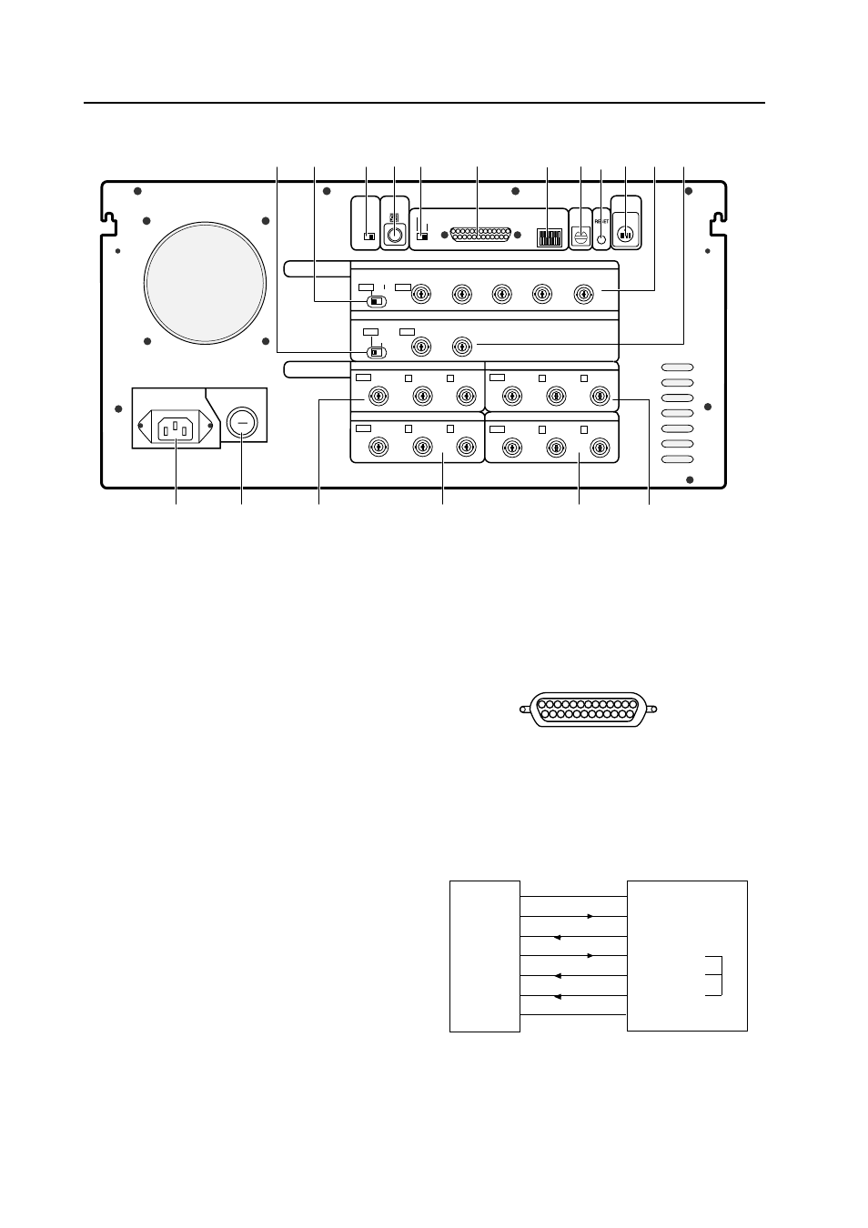
Rear Panel
1 VBS/ Y/C switch
Selects whether the VBS (video signal) or Y/C
signals are input to the V IN (Video) input.
The factory preset is VBS (video signal).
2 V.FIL (Vertical interpolation filter) ON/
OFF switch
When the optional variable scan board (RMD-
V3020) is installed, use this switch to switch the
vertical interpolation filter ON/OFF. Set this
switch to ON if the top and bottom of the com-
puter screen image cannot be accommodated
entirely by the screen.
The factory preset is set to ON.
3 INPUT switch
Selects whether the V IN (Video) or OPTION input
is enlarged into 4 screens.
The factory preset is set to V IN.
* Always press the reset button after changing
the position of this switch.
4 Remote control input connector
Connects the display’s remote control unit.
(Adjustment or changes to the settings of the
unit cannot be accomplished with the remote
control unit.)
5 RS-232C switch
When performing adjustments from a computer,
use this switch to switch between this unit (MVP)
and display (DISPLAY).
6 RS-232C connector
Connects RS-232C cable.
< RS-232C connector diagram >
RS-232C pin layout
13
1
25
14
< RS-232C connection diagram >
Use an RS-232C straight cable for connection.
RS-232C
RS-232C IN connector
straight cable
* Pins 4, 5 and 6 are internally shorted.
• Pins which are not shown in the diagram are not
used.
FG
1
1
FG
TxD
2
2
RxD
RxD
3
3
TxD
RTS
4
4
RTSI
CTS
5
5
CTSI
DSR
6
6
DSRI
SG
7
7
SG